Rigid-Flex PCB
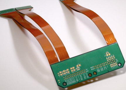
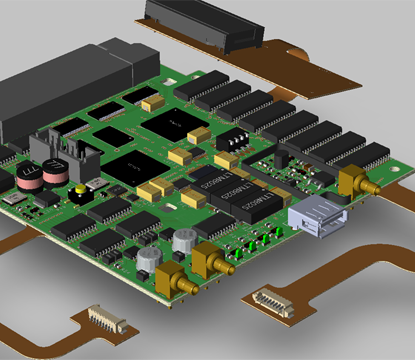
Rigid-Flex PCBs, also known as Rigid-Flexible PCBs, combine flexible and rigid PCB technologies, allowing designers to create complex 3D shapes by twisting, folding, and rolling the flexible substrates to meet the specific requirements of compact and high-performance final assemblies, making them ideal for applications where space, durability, and flexibility are essential, with the flexible substrates designed to remain in a constant state of flex and typically forming curves during manufacturing or installation to optimize the overall design. Rigid-Flex PCBs are composed of multiple layers of flexible PCB materials, such as polyimide, combined with layers of rigid PCB materials, like FR4, offering the unique ability to bend or fold in the flexible sections while providing stability and robust support for components and connectors in the rigid sections. This combination enables the design of compact, lightweight, and highly durable circuit boards that can withstand complex shapes, vibrations, and mechanical stresses. Rigid-Flexible PCBs are widely used across industries like aerospace, automotive, medical devices, consumer electronics, and more. In aerospace, they are found in navigation and avionics systems, while in automotive, they’re used in control units and sensors. Medical devices, such as wearables and implants, benefit from their compact, reliable design. In consumer electronics, they help create lighter, more durable products like smartphones and tablets, offering flexibility and stability in one. Main Features of Rigid-Flex PCB : |
 |
|
 |
1, Combination of rigid and flexible sections: Rigid-Flex PCBs are designed with a combination of rigid and flexible materials, allowing the PCB to bend and flex as needed. This feature enables the PCB to fit into tight spaces, follow complex design requirements, and withstand mechanical stress without compromising functionality. 2, Improved reliability: Rigid-Flex PCBs offer enhanced reliability compared to traditional rigid PCBs. The flexible sections of the PCB help absorb shocks and vibrations, reducing the risk of damage to the board and its components. They also minimize the number of connectors and solder joints, which can be potential points of failure, leading to improved overall reliability. |
|
3, Space-saving design: Rigid-Flex PCBs provide space-saving benefits due to their flexible nature. They can be custom-designed to fit specific dimensions and contours within a device, maximizing the available space for other components or functionalities. This feature is particularly valuable in compact electronic devices with limited space. 4, Simplified assembly: The assembly process for Rigid-Flex PCBs is often simpler and more efficient compared to rigid PCBs. With fewer components and connectors, the overall assembly time and complexity are reduced. This streamlines the manufacturing process and lowers production costs. 5, Cost-effective solution: While Rigid-Flex PCBs may have a higher initial cost compared to standard rigid PCBs, they can offer cost savings in the long run. The elimination of connectors and cables reduces the need for additional components, saving on material costs. Moreover, the improved reliability and durability of Rigid-Flex PCBs can minimize maintenance and repair expenses. 6, Design flexibility: Rigid-Flex PCBs provide greater design flexibility, allowing for complex and customized layouts. The combination of rigid and flexible sections enables the PCB to adapt to various form factors, such as curved or irregular shapes. This versatility opens up new possibilities for innovative product designs and applications. 7, Improved signal integrity: Rigid-Flex PCBs can help maintain signal integrity in high-speed or sensitive electronic systems. The controlled impedance characteristics of the flexible sections prevent signal degradation and electromagnetic interference, ensuring reliable transmission of signals throughout the board. |
||
Main Applications of Rigid-Flex PCB : |
Rigid-Flex PCBs find diverse applications across numerous industries due to their unique combination of rigid and flexible circuitry. Some common applications include: 1, Medical Devices: Rigid-Flex PCBs are utilized in medical devices and equipment where space constraints, reliability, and durability are critical. They can be found in pacemakers, medical imaging devices, diagnostic equipment, wearable health monitors, and various surgical instruments. 2, Automotive Systems: Rigid-Flex PCBs play a vital role in automotive electronics, particularly in advanced driver-assistance systems (ADAS), infotainment systems, engine control units (ECUs), and dashboard displays. They provide the necessary flexibility and reliability for automotive applications. |
|
 |
3, Telecommunications: Rigid-Flex PCBs are integral to telecommunications infrastructure, including base stations, network switches, routers, and communication modules. They enable efficient signal transmission and space optimization in telecommunications equipment. 4, Aerospace and Defense: Rigid-Flex PCBs are used in aerospace and defense applications where lightweight, compact, and reliable circuitry is required. They are employed in avionics systems, military communication devices, radar systems, and missile guidance systems, among others. 5, Consumer Electronics: Rigid-Flex PCBs are extensively used in consumer electronic products such as smartphones, tablets, laptops, digital cameras, and wearable devices. Their ability to conform to the shape of the device and save space makes them well-suited for compact consumer electronics. |
6, Industrial Control Systems: Rigid-Flex PCBs are utilized in industrial control systems, factory automation, robotics, and other industrial applications. Their ruggedness, space-saving design, and resistance to environmental factors make them suitable for demanding industrial environments. 7, Wearable Technology: Rigid-Flex PCBs are increasingly used in wearable technology, including smartwatches, fitness trackers, and electronic textiles. Their flexible nature allows them to conform to the contours of wearable devices while maintaining reliability. 8, Military and Aerospace: Rigid-Flex PCBs are extensively used in military and aerospace applications due to their ability to withstand harsh environments, vibrations, and temperature variations. They are employed in aircraft, spacecraft, satellites, and military communication systems. These examples highlight the diverse and extensive applicability of Rigid-Flex PCBs across various industries, demonstrating their versatility in meeting the demands of a wide range of electronic devices and systems, from compact consumer electronics to complex medical equipment and advanced aerospace technologies, where space optimization, durability, and high performance are crucial. |
|
Advantages of Rigid-Flexible PCB : |
1, Space-Saving: Rigid-Flexible PCBs offer the advantage of being able to fit into available space and dimensions more easily compared to rigid PCBs. The combination of rigid and flexible sections allows the PCB to adapt and bend according to the available space in the device, resulting in significant space savings. 2, Shock and Vibration Resistance: Unlike rigid PCBs, Rigid-Flexible PCBs have better shock and vibration resistance. The flexible sections of the PCB can absorb shocks, preventing breakage and maintaining reliable connections. This makes Rigid-Flex PCBs ideal for applications where there are frequent shocks and vibrations, such as in folding mobile phones. |
|
 |
3, Simple and Fast Assembly Process: Rigid-Flex PCBs have a simpler and faster assembly process compared to rigid PCBs. The entire PCB can be created using a single assembly line, and the assembly itself is easier due to fewer components. In contrast, rigid PCBs require multiple production runs and assembly steps, making the process more time-consuming and complex. 4, High Reliability: Rigid-Flex PCBs provide better reliability due to the reliable connection between the flexible and rigid sections. The connectors and cable assemblies used in rigid PCBs are not as dependable as Rigid-Flex PCBs. With fewer joints and connections, Rigid-Flex PCBs minimize the risk of poor connections, enhancing overall reliability. 5, Easy Testing: Rigid-Flex PCBs undergo a simpler testing process compared to other PCB types. The absence of connectors and cables, along with fewer joints, simplifies the testing procedure and ensures efficient quality control. |
6, Increased Reliability: Rigid-Flexible PCBs eliminate the need for board-to-board connectors, which improves overall reliability. By reducing the number of solder joints, which can be prone to failure, Rigid-Flex PCBs enhance the robustness of the design. This is especially beneficial for designs involving multiple interlinking subcircuits within an enclosure. 7, Lightweight and Cost-Effective: Rigid-Flexible PCBs eliminate the need for connectors and cable assemblies, creating more space for assembly on the PCB. Additionally, the absence of connectors and other connecting assemblies reduces costs. The compact design and reduced number of parts also contribute to lightweight PCBs, making them advantageous for weight-sensitive applications. |
|
Stackups of Rigid-Flex PCB : |
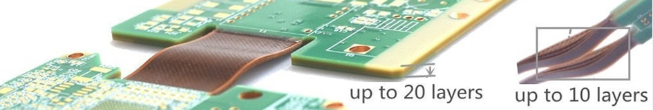
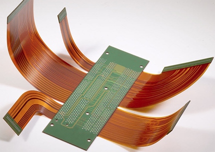
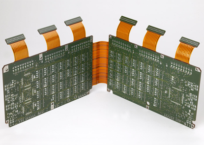
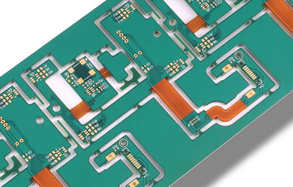
Just like in Rigid PCBs, Flex PCBs and Rigid-Flex PCBs can have complex stackups as more conductive layers are added. These stackups can involve multliple flex sections in the same PCB, such as in the example shown left. For a pure flex circuit the layer stack planning is simplified, including in each section of the PCB. Rigid-Flex PCBs refer to the arrangement of copper and insulating layers within the board, considering both the rigid and flexible sections. The stackup design is essential for ensuring the mechanical integrity, signal integrity, and overall performance of the rigid-flex PCB. A typical stackup of a rigid-flex PCB may consist of the following components : |
|
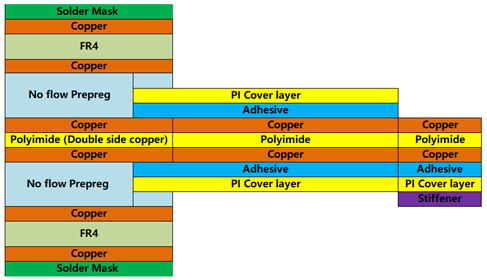 |
1, Rigid Sections: ● Top layer (signal traces, components) 2, Flex Sections: ● Flexible polyimide layer (substrate for flexing) |
The stackup design takes into consideration the specific requirements of the rigid and flexible sections, such as impedance control, bending radius, and mechanical stability. It also accounts for the transition zones where the rigid and flexible sections interface with each other. Each rigid-flex PCB design may have a unique stackup configuration based on the specific application, performance requirements, and manufacturing capabilities. Advanced stackup designs may incorporate multiple rigid and flexible layers to accommodate complex circuitry and demanding mechanical constraints. The stackup of a rigid-flex PCB is carefully engineered to optimize electrical performance, mechanical flexibility, and reliability, making it a critical aspect of the design process for these specialized circuit boards. |
|
Advanced Features of Rigid-Flex PCB : |
 |
1, Pressure Sensitive Adhesives (PSA): In certain applications, PSA with a release liner or 3M sticker is employed to securely fasten specific circuit components within the final product. 2, HDI Rigid-Flex PCB: Rigid-flex PCBs can incorporate High-Density Interconnect (HDI) technology, including buried vias and blind vias in the rigid section with up to 6 layers, while maintaining a 2-layer flex part. 3, Impedance Control: Controlled impedance traces can be implemented in Rigid-Flex PCB designs to minimize electrical reflections and ensure seamless transitions between tracks and interconnections. 4, Panelization: Rigid-Flex PCBs can be partially die-cut with break-out tabs, allowing multiple circuits to remain in a panel during component assembly, especially during processes like wave soldering. |
5, Shielding: Rigid-Flex PCBs can be equipped with shielding to control electromagnetic or electrostatic interference. 6, Laser Cutting: Laser cutting technology is used to precisely trim the flexible portions of PCBs with complex shapes and high-precision tolerances. |
|
Differences Between Flexible And Rigid boards : |
1, Material : Rigid boards are typically made out of FR4 (glass-epoxy compounds) while flexible circuits are made from polyimide (PI). There are cases when rigid boards are built with polyimide, but it isn't as common. |
Design Considerations of Rigid-Flex PCB : |
 |
● Pad Shape: Use fillets (teardrops) with rabbit ears for single-sided flex to capture some of the pad shape with the cover layer. ● Cover Layer: To avoid stress risers (exposing the incoming track), reduce the opening in the cover layer to 220um. ● Conductor Routing: When routing over a flex region, choose a corner style that avoids sharp corners and utilizes curves to minimize stress. ● Through Holes: Avoid designing through holes in the bend area, especially in dynamic application areas. ● Panelization: Orient the flex regions to align with the grain of the material for improved performance during bending. |
● Copper Conservation: Consider how the flex circuit will be panelized to optimize material usage. ● Tear Resistance: Utilize curved corners, drilled holes at corners, holes in slits, and leave metal in corners to enhance tear resistance. ● Service Loop: Make the flex region slightly longer to aid assembly/disassembly and accommodate product dimensional variations (referred to as the service loop). ● Staggered Lengths: Stagger layer lengths by approximately 1.5 times the layer's thickness to prevent layer buckling when flexed. ● Routing: Stagger routes on two-layer boards to avoid "I" beaming and widen routes through the bending zone if possible, especially for permanent bends. ● Static Bend Ratio: Set the ratio of the bend radius to the circuit thickness according to the application type, aiming for a minimum ratio of 13:1 for multi-layer circuits, 8:1 for double-sided circuits, and 6:1 for single-layer circuits. For dynamic applications, aim for a bend ratio of 20:1. ● Copper Selection: Utilize rolled annealed copper for flexible regions, as plated copper is not suitable for flexible areas in rigid-flex PCBs. |
|
Design Guidelines of Rigid-Flex PCB : |
Rigid-Flex PCBs are becoming increasingly popular in a variety of applications, from medical devices to aerospace technology. These boards offer a unique combination of flexibility and rigidity, allowing for complex designs that can integrate multiple functions into a single package. However, designing rigid-flex PCBs requires careful consideration of a number of factors to ensure their reliability and performance. 1, Layer stackup: The layer stackup for a rigid-flex PCB is critical to its functionality. The designer should consider the thickness and type of materials used for each layer, as well as the placement of vias and connectors. Careful attention to the layer stackup can help avoid problems such as signal integrity issues or mechanical failures. |
|
 |
2, Bend radius: One of the key advantages of rigid-flex PCBs is their ability to bend and flex. However, these boards have a minimum bend radius that must be adhered to in order to avoid damage or failure. The designer should determine the minimum bend radius for the PCB based on the materials and thicknesses used, and ensure that components and traces are placed appropriately to accommodate this requirement. 3, Component placement: The placement of components on a rigid-flex PCB is critical to its reliability and performance. Components should be placed to avoid stress points and ensure proper clearance for bending and flexing. Additionally, components should be selected with their intended use in mind, taking into account factors such as temperature range, vibration resistance, and moisture resistance. 4, Trace routing: The routing of traces on a rigid-flex PCB must take into account the board's flexibility and the potential for movement during use. Traces should be routed in a way that avoids stress points and minimizes the risk of cracking or breaking. The designer should also consider the impedance of the traces and ensure that signal integrity is maintained throughout the board. |
5, Via placement: Vias are critical components in a rigid-flex PCB, allowing for connections between the different layers of the board. The designer should carefully consider the placement and size of vias to ensure that they do not interfere with the board's flexibility or cause stress points. 6, Thermal management: Rigid-flex PCBs can generate a significant amount of heat, which can affect their performance and reliability. The designer should consider thermal management techniques such as heatsinks or thermal vias to dissipate heat and prevent damage to the board. Designing a successful rigid-flex PCB requires careful consideration of a number of factors, including layer stackup, bend radius, component placement, trace routing, via placement, and thermal management. By following these guidelines, designers can create reliable and high-performing rigid-flex PCBs for a wide range of applications. |
|
Why Choose PANDA PCB For Rigid-Flexible PCB ? |
Are you in need of high-quality Rigid-Flexible PCBs for your next project ? Look no further! PANDA PCB is the ultimate choice for all your rigid-flex PCB needs. ● Unparalleled Expertise: With years of experience in the industry, Panda PCB boasts a team of highly skilled engineers and technicians who specialize in rigid-flex PCB manufacturing. We have the knowledge and expertise to deliver top-notch solutions that meet your exact specifications. ● Cutting-Edge Technology: At Panda PCB, we embrace the latest technological advancements in PCB manufacturing. Our state-of-the-art facilities are equipped with advanced machinery and software, ensuring precision, reliability, and superior quality in every PCB we produce. |
|
 |
● Customization at its Best: We understand that every project is unique, which is why we offer comprehensive customization options. Whether it's the layer count, material selection, copper weight, or surface finish, we can tailor our Rigid-Flexible PCBs to perfectly align with your specific requirements. ● Rigorous Quality Control: Quality is our utmost priority at Panda PCB. We adhere to stringent quality control measures at every stage of the manufacturing process to ensure that you receive flawless Rigid-Flexible PCBs. Each board undergoes rigorous testing and inspection to guarantee optimal performance and durability. ● Timely Delivery: We value your time and understand the importance of meeting deadlines. With Panda PCB, you can rely on swift and efficient production processes, enabling us to deliver your rigid-flex PCBs within the agreed-upon timeframe. |
● Competitive Pricing: We believe that high-quality PCBs should be accessible to all. Panda PCB offers competitive pricing without compromising on quality. We aim to provide cost-effective solutions that meet your budget requirements without sacrificing excellence. ● Exceptional Customer Support: Our commitment to customer satisfaction goes beyond delivering superior products. We take pride in offering exceptional customer support throughout your entire journey with us. Our dedicated team is readily available to address your queries, provide technical assistance, and ensure a smooth and seamless experience. Choose Panda PCB for your Rigid-Flexible PCB needs and experience the perfect blend of quality, customization, and reliability. Get in touch with us today and let us be your trusted partner in bringing your innovative ideas to life! |
|
Capabilities And Specification of Rigid-Flex PCB : |
Items |
Description |
Production Capabilities |
|
Materials |
Flex raw material(with adhensive) |
ShengYi SF302: PI=0.5mil, 1mil, 2mil, Cu=0.5oz, 1oz Panasonic RF-775/777 : PI=1mil, 2mil, 3mil, Cu=0.5oz,1oz Thinflex: PI=1mil, 2mil, Cu=0.33oz, 0.5oz, 1oz |
Cover film |
ShengYi SF302C: 0515, 0525, 1025, 2030 Thinflex: 0510, 1010 TaiHong FHK: 1025, 1035 |
|
Pure adhensive |
TaiHong : AD=10um, 25um, 40um ShengYi SF302B: AD=25um, 40um TaiHong MHK : PI=3mil, 5mil , 7mil, 9mil |
|
3M tape |
9077, 6677, 9458 |
|
PI Stiffener |
TaiHong MHK : PI=3mil, 5mil , 7mil, 9mil |
|
Normal rigid board material |
IT-180A, S1141, S1000-2 |
|
Special rigid board material |
Arlon: 85N, Rogers: RO4000, Nelco: N4000-13, Ventec: VT-901 |
|
Special Capabilities |
Layer count (flex layer) |
2-12 layers |
Finished board thickness |
0.5mm-3.0mm (rigid) |
|
Board thickness tolerance(>1.0mm) |
board thickness ±10% |
|
Impedance control tolerance |
Singal end: ±5Ω(≤50Ω), ±10%(>50Ω), DIFF: ±5Ω(≤50Ω), ±10%(>50Ω) |
|
Bow and twist(min.) |
0.75%(symmetry), 2%(asymmetry) |
|
Min. distance from conductor to combine place for flex&rigid |
0.5mm(through slot/half slot technolgy) |
|
Suface finish |
OSP, HAL/LF HAL,ENIG, ENPIG, Plating nickel gold copper, Plating soft gold, Plating hard gold, Immerison silver, Immersion Tin |
|
Max panel size |
220mm×400mm |