Metal Core PCB (MCPCB)
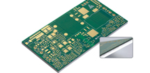
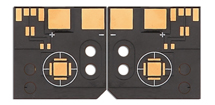
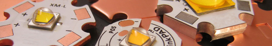
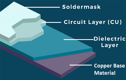
Metal Core PCBs, also known as MCPCBs, are specialized printed circuit boards designed for superior thermal management, featuring a metal substrate, commonly made of materials like aluminum, copper, or iron, that acts as a heat spreader to efficiently dissipate heat, improving the thermal conductivity of the PCB, which is essential for high-power applications involving heat-generating components, with the metal layer typically connected to an insulating material with high thermal conductivity to ensure effective heat transfer, device longevity, and reliability. Metal Core PCBs are characterized by their structure and material composition, with the metal core typically made from aluminum or copper, which can be placed either in the middle or on the back of the PCB, offering exceptional mechanical strength and enhanced durability. Insulating materials with high thermal conductivity, ranging from 1 W/m/K to 398 W/m/K, are used to prevent heat from damaging components and ensure efficient heat dissipation. This combination of materials enables MCPCBs to maintain stable operating conditions even in high-power, high-heat environments. MCPCBs are widely used in applications where thermal management is critical. They are particularly common in high-power devices such as LED lighting systems, power electronics, and automotive electronics. In LED applications, for example, MCPCBs help manage the heat generated by the LEDs, ensuring efficient performance and extending the lifespan of the light sources. Similarly, in power electronics and automotive systems, MCPCBs ensure that sensitive components remain cool under demanding operational conditions, contributing to the overall reliability and efficiency of the devices. Features of Metal Core PCB : |
 |
|
 |
1, Excellent thermal management: The metal core of MCPCB acts as a heat sink, which allows for efficient heat dissipation from the components on the board. This feature is particularly useful in high-power applications where heat can be a concern. 2, High mechanical strength: The metal substrate used in MCPCBs provides excellent mechanical stability and durability, making them ideal for applications that require high resistance to shock and vibration. 3, Improved signal integrity: The metal core in MCPCBs can improve signal integrity by reducing electromagnetic interference and noise. 4, Customizable design: MCPCBs can be customized to meet the specific requirements of the application, including the size, shape, and number of layers. |
|
5, Wide range of thermal conductivity: MCPCBs are available in a wide range of thermal conductivity values, allowing for the selection of the appropriate thermal conductivity level based on the specific needs of the application. 6, Compatibility with surface mount technology (SMT): MCPCBs are compatible with SMT, which allows for easier assembly of components on the board. Metal Core PCBs (MCPCBs) feature superior thermal management through the use of metal substrates such as aluminum or copper, which act as efficient heat spreaders to dissipate heat effectively, ensuring improved thermal conductivity and mechanical strength, while insulating materials with high thermal conductivity help protect sensitive components, making them ideal for high-power, high-heat applications like LED lighting, power electronics, and automotive electronics, where reliable performance, long-term stability, and durability are essential. |
||
Main Difference Between FR4 PCB and Metal Core PCB : |
 |
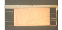
1, Thermal Conductive Dielectric: The key difference between FR4 PCB and MCPCB lies in the thermal conductive dielectric material used in metal core PCBs. The core of an MCPCB is designed to redirect heat away from critical components on the board to less crucial areas such as the metal heatsink backing or metallic core. This is achieved by incorporating a thin dielectric layer that electrically insulates the circuit layer from the metal core while allowing heat from components to transfer to the metal core for dissipation. This feature sets MCPCBs apart from regular FR4 PCBs. 2, Manufacturing Cost: The manufacturing cost of MCPCBs is generally higher than that of FR4 PCBs. The choice of metal substrate for the MCPCB, such as copper, aluminum, or steel, impacts the heat transfer and dissipation properties. While a copper core offers better thermal performance, it also comes at a higher price. As a result, aluminum-based MCPCBs are more commonly selected due to their favorable cost-performance balance. Steel bases, on the other hand, are limited to applications requiring higher mechanical strength and improved thermal conductivity. |
3, Manufacturing Process: The manufacturing process of MCPCBs differs from that of FR4 PCBs. During MCPCB fabrication, a thin layer of dielectric material with both thermal conductivity and electrical insulation properties is added between the copper foil layer and the aluminum core. The copper foil is then etched to create the circuit layer, similar to the process used for regular FR4 boards. 4, Thermal Performance: MCPCBs generally offer superior thermal performance compared to FR4 PCBs. The metal core in MCPCBs acts as an efficient heat sink, allowing for better heat dissipation and thermal management, especially in high-power applications. This enhanced thermal performance is a key advantage of MCPCBs over traditional FR4 boards. 5, Application Specificity: While FR4 PCBs are versatile and widely used in various electronic applications, MCPCBs are specifically designed for applications requiring efficient heat dissipation and thermal management. They are commonly employed in LED lighting, automotive electronics, power supplies, and other high-power electronic devices where thermal considerations are critical. |
|
 |
6, Weight and Thickness: MCPCBs tend to be lighter and thinner than FR4 PCBs, primarily due to the use of a metal core instead of a fiberglass substrate. This difference in weight and thickness can be advantageous in applications where space and weight constraints are important factors. 7, Reliability and Durability: Due to their improved thermal management and mechanical strength, MCPCBs generally exhibit higher reliability and durability compared to FR4 PCBs, especially in environments with temperature variations and thermal cycling. 8, Surface Mount Technology (SMT) Compatibility: MCPCBs are fully compatible with surface mount technology (SMT), allowing for easy assembly of components onto the board. This compatibility is essential for modern electronic manufacturing processes and contributes to the widespread adoption of MCPCBs in various industries. |
What Materials Used for Metal Core PCB ? |
Metal Core PCBs use materials like aluminum, copper, and occasionally special alloys for their metal core, with aluminum being the most common due to its cost-effectiveness, good thermal conductivity, and ease of fabrication. Copper, while more expensive, offers superior thermal conductivity and mechanical strength, making it suitable for high-performance applications. Brass and steel, although harder materials, are less commonly used because they complicate the cutting process, and their chemical compatibility with manufacturing processes can be a concern. The insulating layer typically consists of high-thermal-conductivity epoxy resin, fiberglass, or polyimide to ensure efficient heat dissipation while protecting sensitive components. Additionally, the copper layer is used to form the circuit patterns and may vary in thickness depending on the application's power and thermal requirements. Soldermask and silkscreen layers are also used, similar to traditional PCBs, to protect and identify components. |
Thermal Conductivity of MCPCB : |
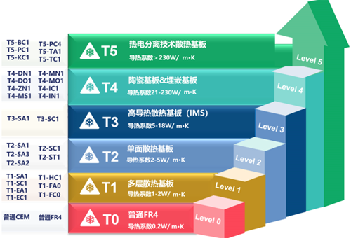 |
MCPCBs are designed to have high thermal conductivity, primarily determined by the metal core material, to efficiently dissipate heat generated by electronic components. The following are typical thermal conductivity ranges for aluminum-based and copper-based MCPCBs: 1, Aluminum-Based MCPCB: The thermal conductivity of aluminum-based MCPCBs ranges from approximately 205-250 W/m·K. 2, Copper-Based MCPCB: The thermal conductivity of copper-based MCPCBs ranges from approximately 386 W/m·K. It's important to note that the overall thermal conductivity of an MCPCB is influenced not only by the metal core but also by the dielectric layer and copper traces. The dielectric material’s thickness and thermal properties, along with the copper trace thickness and layout, can impact the heat dissipation efficiency. Together, these layers determine the MCPCB’s ability to manage heat effectively and maintain reliable performance in high-power applications. |
Product Types of Metal Core PCB : |
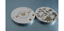
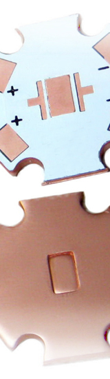
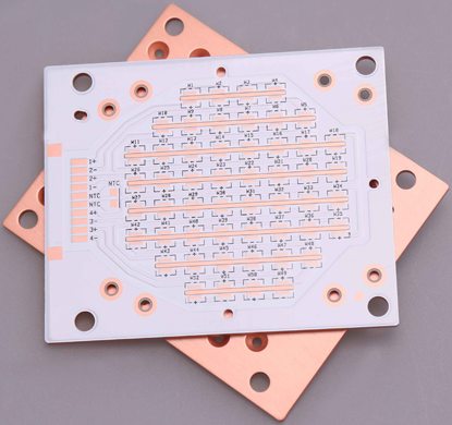
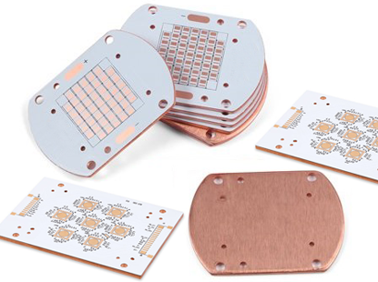
1, Aluminum Core PCB: |
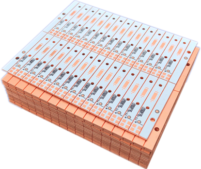
2, Copper Core PCB: The overall structure of copper core PCBs is similar to aluminum core PCBs, but they exhibit superior thermal conductivity, electrical insulation performance, and machining capabilities. Copper core PCBs are well-suited for high-frequency circuit boards, high heat dissipation devices, and precision communication equipment. Copper core is considered the best material for heat radiation due to its excellent heat transfer and dissipation properties. The standard thermal conductivity of copper core PCBs is 2.0 W/m.K, and with excellent insulating layers, this value can be achieved up to 12.0 W/m.K. |
Differences Between Aluminum Core PCB and Copper Core PCB : |
 |
1, Thermal Conductivity: Copper has a higher thermal conductivity compared to aluminum. The thermal conductivity of copper is approximately twice as high as that of aluminum. This means that copper core PCBs can more efficiently transfer heat away from heat-generating components, allowing for better heat dissipation. 2, Fabrication Cost: Aluminum Core PCBs are generally more cost-effective compared to Copper Core PCBs. Copper is a more expensive material, making the production cost of Copper Core PCBs higher. This cost difference can be a significant factor in determining which type of PCB to use, especially in cost-sensitive applications. 3, Weight: Aluminum is a lightweight material, while copper is heavier. This weight difference can be crucial in applications where weight reduction is important, such as portable electronic devices or aerospace applications. Aluminum Core PCBs provide an advantage in terms of lighter weight. 4, Electrical Conductivity: Copper is a superior electrical conductor compared to aluminum. This makes Copper Core PCBs more suitable for high-frequency circuit boards and precision communication equipment, where efficient transmission of electrical signals is critical. |
4, Electrical Conductivity: Copper is a superior electrical conductor compared to aluminum. This makes Copper Core PCBs more suitable for high-frequency circuit boards and precision communication equipment, where efficient transmission of electrical signals is critical. 5, Current-Carrying Capacity: Due to its higher electrical conductivity, copper has a greater current-carrying capacity than aluminum. Copper Core PCBs are preferred when there is a need for thicker copper foils to handle larger currents without significant voltage drops or overheating. 6, Machining: Copper is a harder material compared to aluminum. This can make the machining and fabrication processes for Copper Core PCBs more challenging. Aluminum Core PCBs may be easier to work with in terms of drilling, cutting, and shaping. Based on these differences, the selection between Aluminum Core PCBs and Copper Core PCBs depends on specific application requirements, such as heat dissipation needs, cost considerations, weight restrictions, electrical conductivity requirements, and current-carrying capacity demands. |
|
Advantages of Metal Core PCB : |
1, Better Dimensional Stability: Metal core PCBs exhibit good dimensional stability, making them more resistant to changes in size under varying environmental conditions. For example, when heated from 30°C to 150°C, aluminum-based PCBs and aluminum sandwich panels typically experience a size change of only 1.5% to 2.5%, demonstrating their superior stability compared to insulating materials. 2, Excellent Heat Dissipation: Metal core PCBs excel in heat dissipation due to their ability to integrate a dielectric polymer layer with high thermal conductivity, resulting in lower thermal resistance. Compared to FR-4 PCBs, metal core PCBs transfer heat 8 to 9 times faster, effectively preventing potential damage to circuits or components and ensuring cooler operation of heat-generating components. This enhanced heat dissipation leads to improved performance and extended component lifespan. 3, Enhanced Durability: Metal substrates used in metal core PCBs offer greater durability and conductivity compared to epoxy-based products such as FR-4. The use of aluminum or other metal cores significantly reduces the risk of accidental breakage during PCB manufacturing, assembly, or final product use. The increased strength and durability of metal core PCBs contribute to their long-term reliability. |
|
 |
4, Environmental Resistance: Metal core PCBs exhibit excellent resistance to environmental factors such as moisture, humidity, and temperature fluctuations. They are less prone to warping or delamination, ensuring consistent performance even in harsh operating conditions. 5, Improved Signal Integrity: Metal core PCBs can help enhance signal integrity in high-frequency applications. The metal core provides better grounding and shielding, reducing electromagnetic interference (EMI) and ensuring cleaner signal transmission. This makes metal core PCBs suitable for communication systems, RF devices, and high-speed digital circuits. 6, Higher Power Handling Capability: Metal core PCBs have the ability to handle higher power levels compared to standard FR-4 PCBs. The metal core acts as a heat sink, efficiently dissipating heat generated by power components, thereby preventing overheating and maintaining system reliability. |
7, Design Flexibility: Metal core PCBs offer greater design flexibility compared to ceramic substrates. They can be easily customized and fabricated to meet specific size, shape, and layout requirements. This flexibility allows for efficient integration of complex circuitry, heat sinks, and other components. 8, Compatibility with Surface Mount Technology (SMT): Metal core PCBs are compatible with surface mount technology, making them suitable for high-density assembly of surface mount components. This enables efficient and cost-effective manufacturing processes, especially for small form-factor devices. 9, Lightweight Design: Metal core PCBs, particularly those utilizing aluminum, are lighter in weight compared to ceramic PCBs. The lightweight nature of metal core PCBs not only offers advantages in weight-sensitive applications but also contributes to their longevity. Additionally, metal boards can be etched to control heat flow away from components and provide better electrical conductivity than traditional FR-4 PCBs. Furthermore, metals are non-toxic and recyclable, making metal core PCBs environmentally friendly. 10, Wide Range of Applications: Metal core PCBs find application in various industries, including automotive, LED lighting, power electronics, aerospace, and telecommunications. Their ability to efficiently dissipate heat and provide durability makes them suitable for demanding environments and high-reliability applications. |
|
Fabrication Challenges of MCPCB : |
 |
1, Coefficient of Thermal Expansion (CTE ): For PCB manufacturer, The CTE parameters of all raw materials are important to know clear when developing processes like lamination and HASL with hight temperature, It is critical to understand the operating CTE temperatures for reliable operation of metal core PCBs to avoid any potential risk of delamination. 2, Plated Through Holes: One of the biggest challenge is when metal core PCB designed to be 2-layers circuits and required with plated through holes (PTH) for functional connection between top and bottom side, As you know metal core after drilling will be with some debris in the hole wall, Before PTH plating process, The hole wall after drilling process much have a clean and smooth surface, so remove all the debris to keep a reliable hole wall for plating processs is a challenge for manufacturing. 3, Extremely Tight Tolerances: The outline tolerance of a standard FR4-PCB to be +/- 0.05mm is not special requirement for manufacturing. but many of the mechanical and electrical properties don’t always suitable to MCPCB. In this case, The best outline tolerance based on milling process of MCPCB can only reach to 0.075mm for aluminum core PCB or copper core PCB, If you need to be 0.05mm , then it will use laser cutting process, but it cost higher. |
Applications of Metal Core PCB : |
Applications that generate a large amount of heat often cannot be adequately cooled using just traditional fans. MCPCBs are most widely found in thermal technologies, Using a metal core PCB in these thermal products can help to greatly reduce the heating emitted, Conductive cooling through metal core PCBs are an ideal production option. Please check the main applications as following : |
1, Industrial Power Supplies : |
2, Power Converters : |
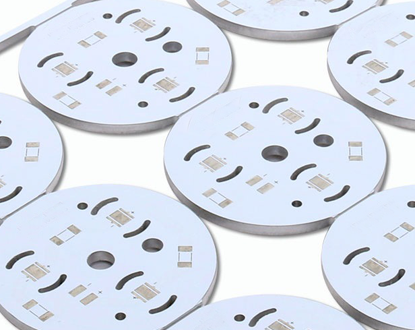
3, LED Lighting : |
4, Office Devices : |
5, Automotive Devices : |
6, Other Devices : |
MCPCB Capabilities : |
Heat-Sink PCB Technologies : |
||||||||||||||||||||||||||||||||||||||||||||||||||||||||||||||
|
1. Post Bonding Technologies(Coin inside,Press fit technology). 2. Pre-bonding (Copper or aluminum based). 3. Sweat Soldering (Based metal sweat soldering). 4. Step Slot technology. 5. Copper and Silver Filled Technology (Copper filled, Silver filled).
|