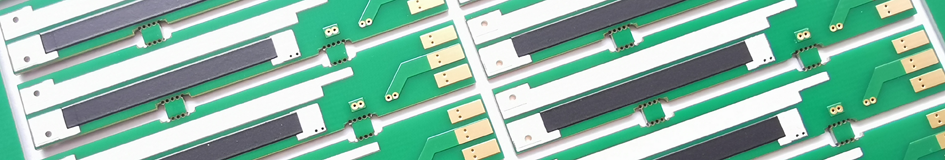
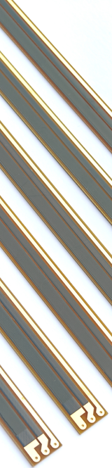
Linear Position Sensor PCB
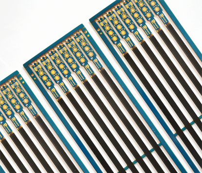
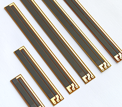
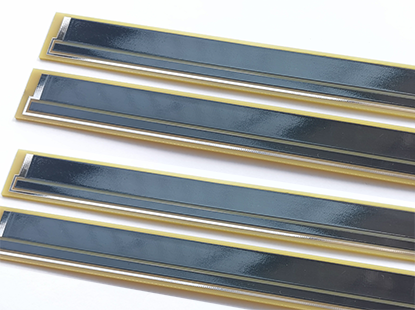
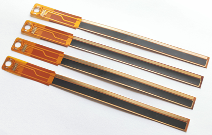
Linear Position Sensor PCBs are customizable, high-precision electronic circuits designed to measure linear displacement or position, integrating thick film resistors (typically in rectilinear resistor tracks) into the printed circuit board to detect resistance changes caused by the rectilinear movement of components (wipers), making them ideal for applications requiring precise position sensing and widely used in motor control, potentiometers, linear measurement systems, robotics, and automation devices, providing stable and accurate feedback to ensure reliable operation in high-performance, highly integrated environments. Linear Position Sensor PCBs, also called Linear Displacement Sensor PCBs, operate on the fundamental principle of serving as voltage dividers. They consist of resistive elements that span the lengths of the sensors, which are connected to sliding contacts or wipers. As the wipers move along the resistive elements, the electrical resistances change proportionally, resulting in changes in voltage outputs. Linear Displacement Sensor PCBs, particularly the contact-based Linear Potentiometer PCBs, are versatile and widely used devices for measuring linear displacement or position. Their simple yet effective designs make them essential components in various industries where precise position feedback is crucial. Main Features of Linear Position Sensor PCB : |
 |
|
 |
1, High Precision: The Linear Position Sensor PCB is designed to provide highly accurate and precise measurement of linear displacement. 2, Signal Conditioning Circuitry: Integrated signal conditioning circuitry ensures that raw sensor data is accurately processed and converted into usable outputs. 3, Customizable Designs: The PCB can be customized to meet specific requirements, including size, shape, and materials used in their construction. 4, Durable Substrates: Depending on the specific application, these PCBs can be designed with durable substrates suitable for the environmental conditions. 5, Compatibility: Linear Position Sensor PCB is designed to be compatible with external systems, facilitating seamless integration into larger electronic systems. |
|
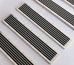
6, Sensing Technology: The PCB incorporates various sensing technologies such as resistive, capacitive, magnetic, or optical principles, depending on the specific application requirements. 7, Cost-Effective Manufacturing: The production of Linear Position Sensor PCBs can benefit from efficient and cost-effective manufacturing processes, contributing to overall affordability. 8, Fabrication Process: The Linear Position Sensor PCB utilizes a screen-printing process to apply a resistive element onto the surface of the PCB. Typically, the resistive paste is printed on two circuit terminals located at opposite ends of the circuits. 9, Main Performances: The main performances of linear position sensor PCBs include resistance value (ohm), sheet resistivity 10ohm-10K-10M (ohm/square), and linearity tolerance (<1.0%), and durability >5 million (life time) etc. 10, Substrates selection: The choice of substrate for the Linear Position Sensor PCB depends on the specific application requirements. Different substrates can be selected as PCB carriers, including the following types: FR4 position sensor PCB, Flexible position sensor PCB, Ceramic position sensor PCB, and PET position sensor PCB. Please refer to Thick Film Potentiometer PCB for more informations. |
||
Applications of Linear Position Sensor PCB : |
 |
1, Automotive: Linear position sensor PCBs are used in automotive applications such as throttle position sensing, suspension systems, accelerator pedal position sensing, and transmission control. 2, Industrial Automation: These sensors are employed in machinery and equipment for precise positioning and control, such as linear actuators, CNC machines, robotic arms, and material handling systems. 3, Medical Devices: Linear position sensor PCBs find application in medical devices like patient positioning systems, prosthetics, imaging equipment, and surgical robots for accurate and precise movement control. 4, Aerospace: These sensors are utilized in aircraft control systems for wing flap control, landing gear positioning, throttle position sensing, and actuator control. 5, Consumer Electronics: Linear position sensor PCBs are integrated into devices such as cameras, joysticks, computer peripherals, gaming consoles, and touch-sensitive screens for user interface and control. |
6, Robotics: These sensors play a crucial role in industrial robots, collaborative robots (cobots), automated guided vehicles (AGVs), and drones for accurate positioning, path planning, and manipulation. 7, HVAC Systems: Linear position sensor PCBs are used in heating, ventilation, and air conditioning systems for damper control and air flow regulation. 8, Packaging Machinery: These sensors are employed in packaging equipment for precise positioning and alignment of products during the packaging process. 9, Agricultural Machinery: Linear position sensor PCBs find application in precision farming equipment for monitoring and control of agricultural processes, such as seed planting, crop spraying, and harvesting. 10, Energy Generation: These sensors are used in wind turbines and solar tracking systems to optimize energy capture by precisely aligning the equipment with the wind or sun. |
|
Advantages of Linear Position Sensor PCB : |
 |
1, Reliability: Linear Position Sensor PCBs are known for their reliability and durability, providing consistent performance over extended periods of operation. 2, Ease of Integration: They are easy to integrate into existing electronic systems and can be customized to fit specific application requirements, facilitating seamless implementation. 3, Compact Design: The compact design of Linear Position Sensor PCBs allows for installation in space-constrained environments without compromising performance. 4, Accurate Measurement: These sensors provide precise and accurate measurement of linear displacement, ensuring reliable and precise positioning information. 5, Durability: Linear position sensor PCBs are designed to be durable and resistant to harsh environmental conditions, ensuring long-term and reliable operation even in demanding applications. 6, Low Maintenance: These sensors have low maintenance requirements, reducing downtime and overall operating costs in industrial settings. |
7, Real-Time Feedback: With their ability to provide accurate and real-time position measurements, linear position sensor PCBs enable immediate feedback for control and monitoring systems. 8, Wide Range of Applications: Linear Position Sensor PCBs find applications in diverse industries such as automotive, aerospace, robotics, and industrial automation due to their versatility and efficiency. 9, Direct Measurement: By directly measuring linear displacement through contact-based sensing, these sensors provide real-time and accurate position feedback essential for precise control systems. Linear Position Sensor PCB stands out for its precision, cost-effectiveness, reliability, ease of integration, and suitability for a wide range of industrial applications, making it a preferred choice for position sensing needs. |
|
Materials Selection of Linear Position Sensor PCB : |
Substrates |
Advantages |
Disadvantages |
|
FR4 |
|
● Cost-Effectiveness: FR4 is the most common PCB substrate material, and due to its widespread use, it is relatively low in cost. ● Good Electrical Properties: FR4 has good insulation and mechanical strength, making it suitable for most electronic applications. ● Easy to Process: FR4 is easy to manufacture and fabricate, compatible with various PCB production techniques. |
● Limited Heat Resistance: Although FR4 can operate at higher temperatures, it has lower heat resistance compared to ceramic substrates. ● Relatively High CTE: This can affect the stability of the circuit under temperature changes. |
Ceramic |
|
● High Thermal Conductivity: Ceramic substrates have excellent thermal conductivity, which is helpful for heat dissipation and suitable for high-power applications. ● Good Electrical Insulation: Ceramic materials have high electrical insulation properties, making them ideal for high-frequency circuits. ● Thermal Stability: Ceramics have a low coefficient of thermal expansion, making them suitable for operation under extreme temperatures. |
● Higher Cost: Compared to FR4, ceramic substrates are more expensive. ● Processing Difficulty: Due to the high hardness of ceramic materials, they are more difficult and costly to process. |
Flex PI |
|
● Flexibility: PI substrates have good flexibility, making them suitable for applications that require bending or curling. ● High-Temperature Resistance: PI substrates can operate stably in high-temperature environments. ● Chemical Resistance: PI substrates have good resistance to a variety of chemicals. |
● Higher Cost: The cost of PI substrates is usually higher than that of FR4. ● Electrical Properties: Although PI substrates have excellent mechanical properties, their electrical properties may not be as good as those of ceramic substrates. |
When selecting a substrate material for Linear Position Sensor PCBs, it is necessary to balance the specific requirements of the application and the budget. For instance, if the application requires high power handling and excellent heat dissipation, ceramic might be a better choice. If considering a balance between cost and electrical performance, FR4 might be a more suitable choice. For applications requiring flexibility, PI substrates are the ideal choice. |
|||
Contact VS Non-Contact of Linear Displacement Sensor PCB : |
In the field of Linear Displacement Sensor PCBs, the traditional contact-based Linear Potentiometer Sensor PCBs differ from other non-contact Linear Position Sensor PCBs in several key aspects including manufacturing process, materials used, working principle, advantages, disadvantages, response time, environmental sensitivity, and durability. 1, Manufacturing Process: 2, Materials Used: |
|
 |
3, Working Principle: 4, Advantages: |
5, Disadvantages: 6, Response Time: 7, Environmental Sensitivity: 8, Durability: Contact-based Linear Potentiometer PCBs and non-contact Linear Position Sensor PCBs exhibit differences in manufacturing process, materials used, working principles, advantages, disadvantages, response time, environmental sensitivity, and durability. The choice between them depends on the specific application requirements, environmental conditions, desired lifespan, and trade-offs between accuracy, simplicity, and cost. |
|
Design Considerations of Linear Position Sensor PCB : |
Designing Linear Position Sensor PCBs with a focus on contact-based potentiometers involves specific considerations to ensure effective performance and reliability. 1, Potentiometer Selection: Choose the appropriate type of potentiometer based on the application requirements, such as conductive plastic, cermet, or wirewound. Consider factors like resolution, linearity, lifespan, and environmental robustness. 2, Mechanical Design: Design the mechanical aspects of the PCB to accommodate the potentiometer's form factor, mounting options, and protection requirements. Ensure proper alignment and stability of the potentiometer within the system to prevent mechanical wear and signal degradation. 3, Electrical Connections: Implement reliable electrical connections between the potentiometer and the PCB, considering factors such as contact resistance, signal integrity, and EMI/RFI interference. Optimize the layout to minimize noise and ensure accurate signal transmission. |
|
 |
4, Wiper Mechanism: Pay special attention to the wiper mechanism of the potentiometer, ensuring smooth and consistent contact with the resistive element. Design features to prevent wiper bounce, arcing, or scratching, which can affect the sensor's accuracy and lifespan. 5, Signal Conditioning: Develop signal conditioning circuitry to process the output signal from the potentiometer effectively. Include amplification, filtering, and calibration components to enhance signal quality, linearity, and noise immunity. 6, Environmental Protection: Shield the potentiometer and PCB against environmental factors such as dust, moisture, temperature variations, and vibrations. Use protective coatings, sealing techniques, or enclosures to enhance durability and reliability in challenging operating conditions. |
7, Calibration and Linearity: Implement calibration procedures to adjust the potentiometer output for accuracy and linearity. Develop testing protocols to verify sensor performance across the full range of motion and under varying loads. 8, Maintenance and Serviceability: Consider ease of maintenance and serviceability in the design, allowing for sensor recalibration, replacement, or troubleshooting when needed. Design the PCB layout for accessibility and modularity to facilitate repairs or upgrades. 9, Longevity and Reliability: Select high-quality potentiometer components, durable materials, and robust manufacturing processes to ensure long-term reliability. Conduct reliability testing and analysis to identify potential failure modes and enhance the sensor's longevity. 10, Integration and Compatibility: Ensure compatibility with the overall system architecture, control interface, and communication protocols. Design the PCB with standard interfaces and connectors for seamless integration into the target application. |
|
Important of Linearity in Linear Displacement Sensor PCB : |
Linearity is a critical aspect in the design and performance of Linear Displacement Sensor PCBs. Linearity refers to the relationship between the physical position or displacement being measured and the corresponding output signal of the sensor. In the context of linear position sensors, linearity indicates how accurately the sensor's output signal follows a straight line in relation to the actual position along its measurement range. 1, Accuracy: Linearity directly impacts the accuracy of the sensor's measurements. A high degree of linearity ensures that the sensor provides precise and consistent output signals proportional to the actual position of the target object. This accuracy is crucial for applications where precise positioning or control is required. |
|
 |
2, Reliability: A linear response is essential for the reliable operation of the sensor over time. Non-linearities in the sensor's output can lead to errors, inconsistencies, and inaccuracies in the measurement data, affecting the overall system performance and reliability. 3, Calibration: Linearity simplifies the calibration process of the sensor, making it easier to adjust and fine-tune the output signals for accurate position tracking. A linear sensor response facilitates calibration procedures and ensures that the sensor behaves predictably across its entire measurement range. 4, System Performance: The linearity of the sensor directly impacts the performance of the overall system in which it is integrated. A linear position sensor contributes to smoother operation, better control, and enhanced efficiency of the system, leading to improved productivity and quality of output. |
5, Signal Processing: Linearity simplifies signal processing tasks and enhances the compatibility of the sensor with data acquisition systems, controllers, and other electronic components. Linear output signals are easier to interpret, process, and integrate into the control algorithms of the system. |
|
Multi-Wire Wipers Used For Linear Position Sensor PCB : |
 |
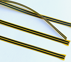
Multi-Wire Wipers are crucial components designed to transmit voltage and signals. They perform linear or rotational sliding over the surfaces of resistive materials (thick film resistors) to adjust resistance values and act as contact elements in voltage dividers. Wiper design is extremely critical for the efficiency and life of the sensor assembly, When designing the wiper, it is very important to consider contact resistance, working-hight (load), repeatability, hysteresis, the resistive material used, and in particular, the wiper material itself, its shape and the wiper pressure. We also provided custom Multi-Wire Wipers (Contact) for customer if needs, we can manufacture the wipers according to customer's design requirements or specification, For more information about wipers, Please refer to Multi-Contact Wipers. |
Engineering Specification of Linear Position Sensor PCB : |
Items : |
Typical Values |
Advanced Capabilities |
1, Substrates : |
FR4, Ceramic ( AI203, ALN, BeO, ZrO2), Polyimide (Flexible PI), Stainless Steel (SUS304), Mica |
FR4, Ceramic ( AI203, ALN, BeO, ZrO2), Polyimide (Flexible PI), Stainless Steel (SUS304), Mica |
2, Conductor (Paste) Materials : |
Copper, Silver , Gold , Silver-Palladium, Palladium-Gold, Platinum-Silver, Platinum-Gold |
Copper, Silver , Gold , Silver-Palladium, Palladium-Gold, Platinum-Silver, Platinum-Gold |
3, Thick Film Carbon Thickness (Height) : |
15um +/-5 um |
30um +/-5 um |
4, Conductor Thickness (Height) : |
12um+/-5um |
20um+/-5um |
5, Min Width of Thick Film Line : |
0.30 mm +/-0.05 mm |
0.20 mm +/-0.05 mm |
6, Min Space of Thick Film Line : |
0.30 mm +/-0.05 mm |
0.20 mm +/-0.05 mm |
7, Min Overlap (Carbon to Conductor) : |
No less than 0.25mm |
0.20mm (Minimum) |
8, Sheet Resistivity (ohms/square): |
Printed resistors in milli ohm to mega ohm range (Customizable) with tolerances of 1-10% are fabricated and protected with overglaze materials |
Printed resistors in milli ohm to mega ohm range (Customizable) with tolerances of 0.5-10% are fabricated and protected with overglaze materials |
9, Resistor Value Tolerance (ohms) : |
+/-10.0% (Standard) (Customizable) |
+/-0.5% (Laser trimming) |
10, Linearity : |
+/-1.0% (Standard) (Customizable) |
+/-0.2 ~ +/-0.5% (Laser trimming) |
11, Synchronism of Double Channels : |
+/-2.0% (Standard) (Customizable) (Potentiometers) |
+/-1.0% (Laser trimming) (Potentiometers) |
12, Durability of Carbon Ink (Life time) : |
0.5 Million (Min), 2.0 Million (Standard) |
5.0-10.0 Million (Max) with Surface Polishing |
13, Working Temperature : |
- 40ºC /+150ºC |
- 40ºC /+180ºC |