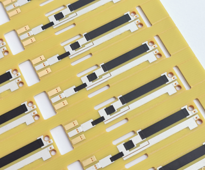
Linear Potentiometer PCB
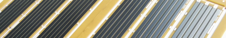
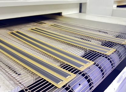
Linear Potentiometer PCBs are custom-designed, specialized circuit boards that integrate variable resistors or sensors into printed circuit boards, optimizing component layout and saving space, with users able to directly mount the wiper to adjust the resistance value along a linear path, making them efficient for applications like audio equipment, position sensors, and frequency adjustment systems, which utilize thick film resistor technology with substrates such as PI, FR4, or ceramics, and undergo a manufacturing process that involves sequential printing of conductive, resistive, and insulating materials, followed by high-temperature sintering and laser trimming to create high-precision linear resistor tracks. Linear Potentiometer PCBs, also called Linear Potentiometer Sensor PCBs, provide linear changes in resistance as the sliding contacts move. This typically involves creating tracks or paths on the PCBs to serve as the resistive elements and attaching metal contacts to sliding mechanisms that move along these tracks. As the contacts move along the tracks, they change the resistance of the potentiometers, allowing for control of various aspects of electronic circuits. Linear Potentiometer Sensor PCBs can utilize various substrates as carriers, depending on the applications. These options encompass FR4, Polyimide (PI), or Ceramic potentiometer PCBs. Furthermore, Linear Potentiometer Sensor PCBs can be classified as Linear-Taper Potentiometer PCBs or Non-Linear Logarithmic Taper Potentiometer PCBs based on their modes of operation. Main Features of Linear Potentiometer PCB : |
 |
|
 |
1, Integration: The linear potentiometer is incorporated directly onto the printed circuit board, eliminating the need for external wiring and connections. 2, Variable Resistance: The linear potentiometer on the PCB allows for continuous adjustment of resistance along its track, providing precise control over the output voltage or signal level. 3, Linear Response: As the sliding contact moves along the resistive track, the change in resistance is linear, meaning that the output voltage or signal level changes proportionally to the position of the sliding contact. 4, Compact Design: By integrating the potentiometer onto the PCB, the overall size and footprint of the component are minimized, making it suitable for space-constrained applications. |
|
5, Customizable: Linear Potentiometer PCBs can be designed and manufactured to meet specific requirements such as resistance range, track length, and physical dimensions, allowing for customization according to the application needs. 6, Different Substrates: Depending on the specific application and environmental factors, various substrate materials can be used for the PCB, such as FR4, Polyimide, Ceramic, or PET, offering flexibility in terms of durability, temperature tolerance, and performance. 7, Mode of Operation: Linear Potentiometer PCBs can be categorized into Linear-Taper or Non-Linear Logarithmic Taper, depending on the desired response curve and application requirements. These features make Linear Potentiometer PCBs versatile components for applications requiring variable resistance control, such as audio equipment, lighting controls, robotics, and industrial automation systems. Please refer to Thick Film Potentiometer PCB for more informations. |
||
Applications of Linear Potentiometer PCB : |
 |
1, Audio Equipment: Linear Potentiometer PCBs are commonly used in audio equipment, such as mixers, amplifiers, and equalizers, to control volume, balance, and tone. 2, Lighting Controls: Linear Potentiometer PCBs are used in lighting systems to adjust brightness, color temperature, and color output, providing precise control over the lighting environment. 3, Robotics: Linear Potentiometer PCBs are used in robotics for position sensing, motion control, and feedback systems. 4, Industrial Automation: Linear Potentiometer PCBs are used in industrial automation systems for machine control, process monitoring, and instrumentation. 5, Medical Devices: Linear Potentiometer PCBs are used in medical devices such as diagnostic equipment, patient monitoring systems, and surgical instruments. |
6, Consumer Electronics: Linear Potentiometer PCBs are used in various consumer electronics products, including gaming controllers, remote controls, and portable audio devices. 7, Automotive: Linear Potentiometer PCBs are used in automotive applications for controlling vehicle functions such as headlights, windshield wipers, and climate control. 8, Aerospace: Linear Potentiometer PCBs are used in aerospace applications for flight control systems, navigation systems, and instrumentation. The versatility and precision of Linear Potentiometer PCBs make them a reliable solution for applications requiring variable resistance control, offering improved performance, accuracy, and flexibility. |
|
Advantages of Linear Potentiometer PCB : |
 |
1, Integration: By incorporating the potentiometer directly onto the PCB, it eliminates the need for additional wiring and connections, resulting in a more compact and simplified design. 2, Space Efficiency: The integration of the potentiometer onto the PCB allows for a smaller overall footprint, making it ideal for applications with limited space or compact electronic devices. 3, Precise Control: Linear Potentiometer PCBs provide precise control over resistance and output voltage, allowing for accurate adjustments and fine-tuning in electronic circuits. 4, Durability: The use of high-quality substrate materials, such as FR4 or Ceramic, ensures the durability and reliability of the PCB, making it suitable for demanding environments and extended usage. 5, Ease of Installation: With the potentiometer already mounted on the PCB, installation becomes easier and faster, reducing assembly time and effort. |
6, Customizability: Linear Potentiometer PCBs can be customized according to specific application requirements, including resistance range, track length, dimensions, and taper type, providing flexibility for various design needs. 7, Cost-Effectiveness: Integrating the potentiometer onto the PCB reduces the need for additional components and simplifies assembly, resulting in cost savings and improved manufacturing efficiency. 8, Compatibility: Linear Potentiometer PCBs are designed to be compatible with standard electronic components and can be easily integrated into existing circuits or systems. The advantages of Linear Potentiometer PCBs make them a practical and efficient solution for applications requiring variable resistance control, offering space savings, precision, durability, and customization options. |
|
How Does Linear Potentiometer PCB Work ? |
● Linear Potentiometer PCB operates by utilizing a resistive element on the PCB, with both end terminals connected to thick film resistors. When the knob is moved, the wiper travels along the resistor strip, resulting in varied resistance. The proximity of the multi-wire wiper to the terminal it is wired with affects the resistance. Closer proximity leads to lower resistance due to a shorter current path, while greater distance results in higher resistance. For instance, when the sliding contact is at the midpoint, the variable resistance value is half of the full-scale resistance of the potentiometer. In this type of potentiometer, the multi-wire wiper moves along a linear path and is also known as a slide pot, slider, or fader. Similar to the rotary-type potentiometer, the sliding wiper rotates on the resistor linearly. The connection of the resistor’s two terminals is linked across the voltage source. A sliding wiper on the resistor can be moved using a path that is connected through the resistor. |
|
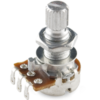
● Rotary Potentiometer PCB uses a strip of carbon resistive material with uniform density around its circumference. The resistance between the center terminal and either end terminal changes at a consistent rate as the control shaft rotates. In the majority of available variable resistors, this relationship is linear, signifying that the relative position corresponds to the resistance ratio. This type of potentiometer includes two terminal contacts where a steady resistance is distributed in a semi-circular pattern. Additionally, it features a middle terminal connected to the resistance via a sliding wiper operated by a rotating knob. The sliding wiper can be adjusted by turning the knob over the semi-circular resistance. The voltage can be obtained between the two resistance contacts and the sliding wiper. Rotary potentiometer PCBs are employed wherever precise voltage control is required. |
|
Types of Linear Potentiometer PCB : |
 |
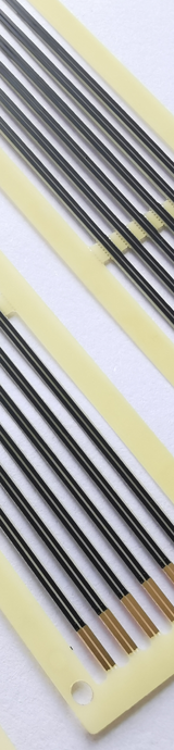
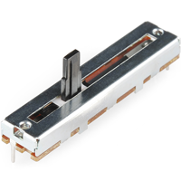
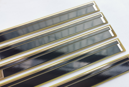
Linear Potentiometers PCB also called slider or fader potentiometers, consist of an adjustable multi-wire wiper that moves in a linear motion. Linear potentiometers PCB are commonly used to measure the resistance of voltage.The thick film resistive material is printed to a track alongside which the multi-wire wiper moves. Linear potentiometers PCB are further divided into four types: 1, Motorized Fader Potentiometer : consists of an automatically adjusted wiper controlled by a servo motor. 2, Multi-Turn Slide Potentiometer : consists of a spindle that allows multiple rotations and provides increased precision. 3, Dual-Slide Potentiometer : consists of a single wiper that controls two potentiometers simultaneously. 4, Slide Potentiometer : consists of a single linear swiper. Please check more details as following : |
Type |
Description |
Applications |
Slide pot |
Single linear slider potentiometer, for audio applications also known as a fader. High quality faders are often constructed from conductive plastic. |
For single channel control or measurement of distance. |
Dual-slide pot |
Dual slide potentiometer, single slider controlling two potentiometers in parallel. |
Often used for stereo control in professional audio or other applications where dual parallel channels are controlled. |
Multi-turn slide |
Constructed from a spindle which actuates a linear potentiometer wiper. Multiple rotations (mostly 5, 10 or 20), for increased precision. |
Used where high precision and resolution is required. The multi turn linear pots are used as trimpots on PCB, but not as common as the worm-gear trimmer potentiometer. |
Motorized fader |
Fader which can be automatically adjusted by a servo motor. |
Used where manual and automatic adjustment is required. Common in studio audio mixers, where the servo faders can be automatically moved to a saved configuration. |
Design Considerations for Linear Potentiometer Sensor PCB : |
1, Selection of Substrate Material: |
|
 |
2, Circuitry Design: 3, Taper Type: |
4, Mechanical Considerations: 5, Environmental Considerations: |
|
Linearity Definition of Linear Potentiometer PCB : |
1, The linearity of a linear potentiometer PCB refers to the relationship between the physical position of the wiper and the corresponding resistance value. In a perfectly linear potentiometer, the ratio of the wiper position to the total resistance should remain constant throughout the full range of motion. This means that if the wiper is moved a quarter of the way along the resistor strip, the resistance value should be one-quarter of the full-scale value. Similarly, if the wiper is moved three-quarters of the way along the strip, the resistance value should be three-quarters of the full-scale value. |
|
 |
2, In practical applications, it's difficult to achieve perfect linearity, and there may be some deviations from the ideal linear relationship. The degree of deviation from linearity is usually expressed as a percentage of the full-scale value, known as the linearity error. A lower linearity error indicates a more precise and accurate linear potentiometer. The linearity of a linear potentiometer is a critical factor in applications such as audio mixing consoles, where precise control over the signal level is essential. 3, Linearity is an important characteristic for applications where precise and accurate position sensing is required. It ensures that the potentiometer provides a consistent and predictable response to changes in position, making it suitable for applications such as volume control, position control, and user interface input devices. |
4, The typically specify the linearity of a potentiometer as a percentage of the maximum deviation from a perfectly linear response. For example, a potentiometer with a linearity specification of ±1% means that the actual output may deviate from a perfect linear relationship by up to 1% of the full-scale range. 5, Linearity is the deviation of the output characteristic curve as compared to an ideal straight line. It is measured by the greatest deviation from the ideal straight line with respect to the applied voltage. The deviation is given in %. Essentially three types of nonlinearities can be provided for potentiometer sensor specifications: ● Independent Linearity: This type of linearity considers the deviation of the output characteristic curve independently, without reference to any other variables or conditions. ● Absolute Linearity: Absolute linearity takes into account the overall deviation of the output characteristic curve, considering all possible factors and conditions. ● Terminal Linearity: Terminal linearity focuses on the deviation of the output characteristic curve at the ends or terminals of the sensor's measurement range. 6, The required type of linearity and linearity deviation should always be customized for the each specific application, For example can be 0.25% or 0.5% by laser trimming process, Specifying a percentage of linearity - without further information - automatically implies independent. |
|
How Important Role of Linearity in Linear Potentiometer PCB ? |
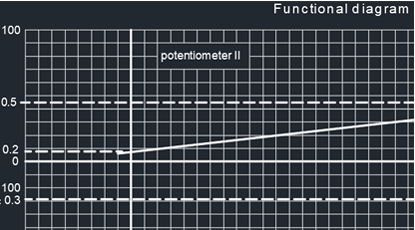
● The role of linearity in linear potentiometer PCBs is crucial as it directly impacts the accuracy and precision of position sensing or voltage division. Linearity refers to the relationship between the physical position of the potentiometer wiper and the resulting electrical output, typically represented as a straight line on a graph. In the context of linear potentiometer PCBs, maintaining high linearity ensures that small changes in position correspond to consistent and predictable changes in resistance or voltage output. |
|
 |
● High linearity is essential for applications that require precise and proportional measurement of linear displacement or position. For example, in control systems, instrumentation, or user interface devices, accurate and predictable voltage division is necessary for achieving precise control or feedback. Additionally, in position sensing applications, such as in robotics or automotive systems, linearity ensures that the measured position accurately reflects the actual physical position of the object being monitored. ● The role of linearity in linear potentiometer PCBs is critical for ensuring reliable and accurate performance in a wide range of applications where precise linear measurement or control is essential. Maintaining high linearity allows for consistent and predictable voltage division, contributing to the overall reliability and functionality of the system in which the linear potentiometer PCB is employed. |
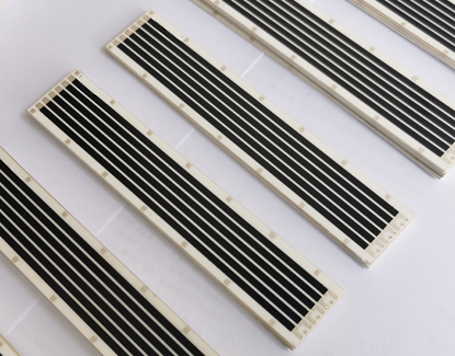
Multi-Wire Wipers Used For Linear Potentiometer PCB : |
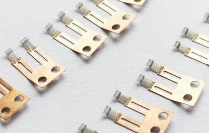 |
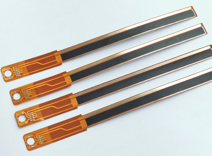
Multi-Wire Wipers are crucial components designed to transmit voltage and signals. They perform linear or rotational sliding over the surfaces of resistive materials (thick film resistors) to adjust resistance values and act as contact elements in voltage dividers. Wiper design significantly impacts the efficiency and lifespan of the sensor assembly. When designing the wiper, it is essential to consider factors such as contact resistance, operating load, repeatability, hysteresis, the resistive material used, as well as the wiper material, its shape, and the applied wiper pressure. We also offer custom Multi-Wire Wipers (contact) tailored to the specific needs of our customers. We can manufacture wipers according to the customer's design requirements or specifications. For more information about Multi-Wire Wipers, please refer to the section on Multi-Contact Wipers. |
Engineering Specification of Linear Potentiometer PCB : |
Items : |
Typical Values |
Advanced Capabilities |
1, Substrates : |
FR4, Ceramic ( AI203, ALN, BeO, ZrO2), Polyimide (Flexible PI), Stainless Steel (SUS304), Mica |
FR4, Ceramic ( AI203, ALN, BeO, ZrO2), Polyimide (Flexible PI), Stainless Steel (SUS304), Mica |
2, Conductor (Paste) Materials : |
Copper, Silver , Gold , Silver-Palladium, Palladium-Gold, Platinum-Silver, Platinum-Gold |
Copper, Silver , Gold , Silver-Palladium, Palladium-Gold, Platinum-Silver, Platinum-Gold |
3, Thick Film Carbon Thickness (Height) : |
15um +/-5 um |
30um +/-5 um |
4, Conductor Thickness (Height) : |
12um+/-5um |
20um+/-5um |
5, Min Width of Thick Film Line : |
0.30 mm +/-0.05 mm |
0.20 mm +/-0.05 mm |
6, Min Space of Thick Film Line : |
0.30 mm +/-0.05 mm |
0.20 mm +/-0.05 mm |
7, Min Overlap (Carbon to Conductor) : |
No less than 0.25mm |
0.20mm (Minimum) |
8, Sheet Resistivity (ohms/square): |
Printed resistors in milli ohm to mega ohm range (Customizable) with tolerances of 1-10% are fabricated and protected with overglaze materials |
Printed resistors in milli ohm to mega ohm range (Customizable) with tolerances of 0.5-10% are fabricated and protected with overglaze materials |
9, Resistor Value Tolerance (ohms) : |
+/-10.0% (Standard) (Customizable) |
+/-0.5% (Laser trimming) |
10, Linearity : |
+/-1.0% (Standard) (Customizable) |
+/-0.2 ~ +/-0.5% (Laser trimming) |
11, Synchronism of Double Channels : |
+/-2.0% (Standard) (Customizable) (Potentiometers) |
+/-1.0% (Laser trimming) (Potentiometers) |
12, Durability of Carbon Ink (Life time) : |
0.5 Million (Min), 2.0 Million (Standard) |
5.0-10.0 Million (Max) with Surface Polishing |
13, Working Temperature : |
- 40ºC /+150ºC |
- 40ºC /+180ºC |