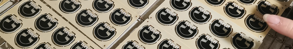
Carbon Potentiometer PCB
Carbon Potentiometer PCBs, also called Potentiometer Carbon PCBs, are customizable, specialized printed circuit boards integrated with variable resistors, utilizing thick film resistor technology to print carbon film onto various substrates (PI, FR4, and ceramics), followed by high-temperature sintering and laser trimming to form durable, stable resistive tracks, with resistor values effectively changed by adjusting the positions of the wipers on the resistive tracks, enabling precise control of voltage output, making them highly suitable for applications requiring fine-tuning and continuous voltage adjustment, such as audio equipment, industrial controls, automotive electronics, and sensor calibration. Carbon potentiometer PCBs are designed to support the mechanical and electrical components of potentiometers, ensuring secure and reliable connections within the overall circuit. They provide the necessary tracks and pads for the potentiometer terminals, facilitating seamless integration into electronic devices for a variety of applications, such as volume control, position sensing, and gain adjustment in amplifiers. Carbon potentiometers are renowned for their durability and excellent tracking characteristics, making them suitable for a broad range of applications across different industries. Potentiometer Carbon PCBs enable the implementation of Linear, Rotary, and Logarithmic Taper potentiometer functions. This technology involves integrating the potentiometer module directly onto the PCB surface, which not only optimizes assembly space but also offers multiple design options for product developers. Additionally, this approach significantly reduces manufacturing costs, making it a highly efficient solution for both performance and budget considerations. Key Features of Carbon Potentiometer PCB : |
 |
|
 |
1, Integration: The PCB integrates a carbon-based potentiometer directly onto the board, eliminating the need for separate potentiometer components. 2, Space-Saving: By incorporating the potentiometer functionality into the PCB, it effectively saves space in the overall system or device. 3, Functionality: The Carbon Potentiometer PCB can achieve the functions of linear, rotary, and logarithmic taper potentiometers, providing versatility for various applications. 4, Cost-Effective Manufacturing: This technology helps to reduce manufacturing costs by integrating potentiometer functionality directly into the PCB, streamlining assembly processes. |
|
|
5, Customization Options: PCB designers have the flexibility to customize the potentiometer layout and configuration to meet specific application requirements. 6, Precise Electrical Control: The integrated carbon potentiometer provides precise and smooth control of electrical signal levels within the circuit. 7, Durability: Carbon potentiometers are known for their durability and long service life, as the carbon track resists wear over repeated use. 8, Compatibility: The design is compatible with various types of potentiometer mechanisms, allowing for a range of movement and adjustment capabilities. 9, Noise Characteristics: They typically have low noise characteristics, making them suitable for audio applications where signal clarity is important. 10, Environmental Stability: Carbon potentiometers are less susceptible to environmental changes such as temperature and humidity, ensuring stable performance over a wide range of conditions. Please refer to Thick Film Potentiometer PCB for more informations. |
||
How Carbon Potentiometer PCB Worked as a Voltage Divider ? |
 |
● A Potentiometer Carbon PCB achieves the function of a voltage divider through its working principle by utilizing a resistive element, typically made of carbon, printed on the PCB substrate. This resistive element is connected between two terminals, forming a continuous path with a specific resistance value. When a voltage is applied across the two outer terminals of the potentiometer, a variable output voltage can be obtained by tapping into the resistive element at a point along its length using a sliding contact-wiper. ● As the contact-wiper moves along the resistive element, the effective length of the resistive path changes, altering the ratio of resistances on either side of the tap point. This variation in resistance ratios results in a corresponding change in the output voltage at the tap point. By adjusting the position of the sliding contact-wiper, users can precisely control the output voltage within a specific range, effectively dividing the input voltage as required. In essence, the potentiometer carbon PCB acts as a voltage divider by providing a variable output voltage proportional to the position of the contact-wiper along the resistive element. |
Main Performances of Carbon Potentiometer PCB : |
|
1, Resistance Value: The resistance value of a carbon potentiometer PCB refers to the overall resistance offered by the carbon resistive element printed on the PCB substrate, typically measured in ohms. This value determines the degree of resistance the PCB can provide when used as a variable resistor in a circuit. 2, Resistive Sheet (Ohm/Square): The resistive sheet, measured in ohms per square, indicates the uniformity and consistency of resistance across the surface area of the carbon resistive element on the PCB. A lower resistive sheet value signifies a more evenly distributed resistance, ensuring stable and accurate performance. |
|
 |
3, Linearity: Linearity in a carbon potentiometer PCB denotes the degree to which the relationship between the position of the sliding contact-wiper and the output voltage remains proportional and consistent. High linearity, expressed as a percentage (e.g., <1.0%), indicates minimal deviation from the ideal linear response, leading to precise and predictable voltage adjustments. 4, Temperature Coefficient: The temperature coefficient is an important performance parameter of a carbon potentiometer PCB, which indicates the change in resistance with variations in temperature. It is expressed in parts per million per degree Celsius (ppm/°C) and determines the stability of the resistor's value under different temperature conditions. 5, Durability (Life Time): Durability of a carbon potentiometer PCB refers to its ability to withstand mechanical stress, environmental factors, and prolonged use without significant degradation in performance. Factors such as the quality of materials, construction techniques, and operational conditions contribute to the PCB's long-term reliability and resilience in various applications. |
|
6, Power Rating: The power rating of a carbon potentiometer PCB specifies the maximum amount of power that the PCB can safely handle without causing damage or affecting its performance. It is typically measured in watts and depends on factors such as the size and design of the PCB. Choosing a carbon potentiometer PCB with an appropriate power rating ensures that it can effectively handle the power requirements of the circuit without overheating or failure. |
|
Typical Applications of Carbon Potentiometer PCB : |
|
1, Audio Equipment: Carbon potentiometers are often used in audio equipment such as amplifiers, mixers, and speakers to control volume, tone, and other audio settings. |
|
 |
2, Industrial Control Systems: They are used in industrial control systems for adjusting parameters such as speed, temperature, and pressure in manufacturing and process control applications. 3, Consumer Electronics: Carbon potentiometers can be found in consumer electronics like televisions, radios, and home appliances for user interface controls and adjustments. 4, Automotive Electronics: They are used in automotive applications for controlling features such as dashboard displays, pedal sensor, climate control systems, and audio systems. 5, Instrumentation: Carbon potentiometers are utilized in various types of measuring instruments and test equipment for precise adjustment and calibration. 6, Lighting Controls: They are used in lighting systems for adjusting brightness levels and dimming functions in residential, commercial, and industrial lighting applications. |
7, Medical Devices: Carbon potentiometers find applications in medical devices such as patient monitoring equipment, diagnostic instruments, and laboratory devices. These are just a few examples of the many applications where carbon potentiometer PCBs are used to provide variable resistance and control electrical signals in electronic circuits. |
|
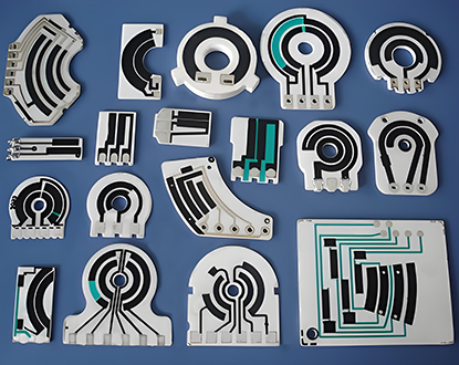
Product Types of Potentiometer Carbon PCB : |
|
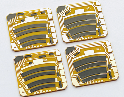
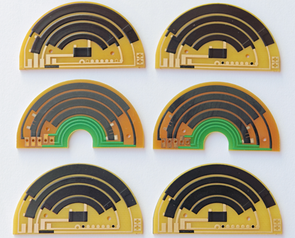
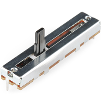
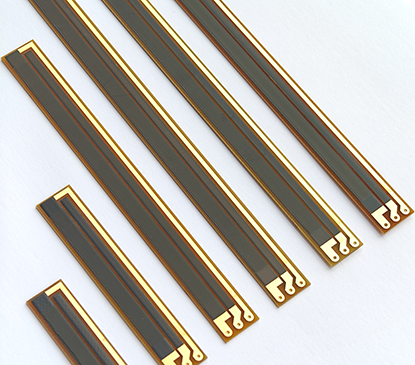
● Characteristics: Linear potentiometer PCBs feature a linear sliding motion for adjusting the control setting. They have a similar three-terminal design, with a wiper moving along a linear resistive element to vary the resistance. This linear motion allows for direct and predictable changes in resistance based on the physical position of the slider. ● Applications: Linear potentiometers are often used in applications where linear adjustments are needed, such as in fader controls for audio mixing consoles, motor speed controls, and user interface sliders in electronic devices. Their linear motion enables them to provide precise and consistent resistance changes, making them suitable for applications that require linear control or positioning. |
|
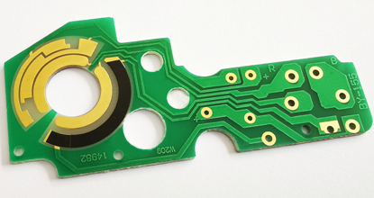 |
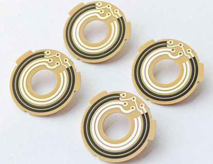
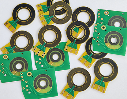
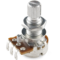
● Characteristics: Rotary potentiometer PCBs are designed with a circular form factor, allowing for rotational adjustment of the control knob. They typically have a three-terminal design, with the wiper rotating along a resistive element to change the resistance value. ● Applications: These potentiometers are commonly used in devices where continuous adjustment is required, such as volume controls in audio equipment, tuning controls in radios, and parameter adjustments in industrial control systems. Their rotational nature makes them well-suited for applications where users need precise, analog control over a variable parameter. |
Both rotary and linear potentiometer PCBs offer variable resistance capabilities, but their different form factors and modes of operation make them suitable for distinct sets of applications. Whether it's rotational adjustment or linear sliding control, these potentiometers play crucial roles in providing analog input and control in various electronic systems. |
|
Operational Mechanisms of Carbon Potentiometer PCB : |
|
● Linear Potentiometer PCB works by having a resistive element on the PCB. Both end terminals are attached to thick film resistor, The wiper travels along the resistor strip when the knob is moved. The closer the multi-wire wiper is to the end terminal it is wired in conjunction with, the less the resistance, because the path of the current will be shorter. The further away it moves from the terminal, the greater the resistance will be. For example, when the sliding contact is at the middle position, the variable resistance value is half of the full-scale resistance of the potentiometer. |
|
|
● Rotary Potentiometer PCB uses a strip of carbon resistive material with constant density all the way around. The resistance between the center terminal and either end terminal changes at a steady rate as the control shaft rotates, The resistance between the middle terminal and-either end terminal constitutes a linear finction of the angular shaft position. In the majority of variable resistors available this is a linear relationship, meaning that the relative position is equal to the resistance ratio. |
|
Key Design Considerations for Potentiometer Carbon PCB : |
When designing Potentiometer Carbon PCBs, several important factors need to be taken into consideration to ensure optimal performance and reliability. These key design considerations include: 1, Substrate Selection (FR4, PI, or Ceramic): Choose the appropriate substrate material based on factors such as thermal conductivity, mechanical strength, and cost considerations. The substrate material affects the PCB's performance, reliability, and manufacturability, so select the most suitable option for your carbon potentiometer PCB design. |
|
 |
2, Resistance Range: Determine the required resistance range that suits the intended application. Carbon potentiometers are available in various resistance values, so selecting the appropriate range is crucial. 3, Power Rating: Consider the power rating requirements to ensure the potentiometer can handle the maximum power dissipation without overheating or causing performance degradation. The power rating should be chosen based on the expected current flowing through the circuit. 4, Tolerance and Linearity: Determine the acceptable level of tolerance and linearity required for accurate voltage or signal control. Tolerance refers to the permissible deviation from the nominal resistance value, while linearity ensures a consistent change in resistance with respect to the control knob's position. 5, Temperature Coefficient: Evaluate the temperature coefficient of the potentiometer, which indicates how the resistance changes with temperature fluctuations. Choose a potentiometer with a low temperature coefficient to minimize the impact of temperature variations on the circuit's performance. |
6, Mechanical Durability: Consider the mechanical durability of the potentiometer, especially if it will be subjected to frequent adjustments or harsh operating conditions. Ensure that the potentiometer can withstand vibrations, shocks, and mechanical wear over its expected lifespan. 7, Mounting Options: Determine the appropriate mounting style for your specific application. Carbon potentiometers can be mounted through-hole or surface-mounted, so select the mounting option that aligns with your PCB design and assembly process. 8, Environmental Factors: Take into account environmental factors such as humidity, dust, and chemical exposure. Choose potentiometers with appropriate protection or sealing to ensure reliable operation in the target environment. 9, Noise and Signal Integrity: Consider the impact of electrical noise on the potentiometer's signal integrity. Select potentiometers with features like shielding or noise reduction mechanisms to minimize interference and ensure accurate signal control. |
|
Important Role of Linearity in Carbon Potentiometer PCB : |
● The linearity in carbon potentiometer PCBs plays a crucial role in ensuring accurate voltage or signal control. Linearity refers to the consistent relationship between the position of the control knob or slider and the resulting change in resistance. In other words, it ensures that as the knob is adjusted, the resistance changes in a predictable and proportional manner. |
|
 |
● The importance of linearity lies in its impact on the precision and reliability of the potentiometer's output. When a potentiometer exhibits high linearity, the output signal or voltage changes in direct proportion to the physical movement of the control mechanism. This is essential in applications where precise control over voltage or signal levels is required. ● For example, in audio equipment or instrumentation, a non-linear potentiometer could lead to inconsistent volume control or inaccurate measurement readings. In contrast, a highly linear potentiometer ensures that small adjustments to the control result in proportional changes to the output, leading to smooth and accurate control. ● Therefore, in carbon potentiometer PCBs, maintaining linearity is critical for achieving the desired performance characteristics and ensuring that the potentiometer reliably and accurately responds to user input or environmental conditions. It directly contributes to the overall functionality and effectiveness of the potentiometer in various electronic circuits and systems. |
|
● During the production of carbon potentiometer PCBs, Carbon printing process once can achieve a resistance tolerance of ±10% with a linearity of ±1.0% without laser trimming. If customers require a linearity of less than 1.0% (e.g., 0.5% or 0.25%), then laser trimming process becomes necessary for adjusting linearity. |
|
Multi-Wire Wipers Used For Carbon Potentiometer PCB : |
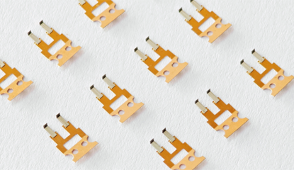 |
Multi-Wire Wipers are crucial components designed to transmit voltage and signals. They perform linear or rotational sliding over the surfaces of resistive materials (thick film resistors) to adjust resistance values and act as contact elements in voltage dividers. Contact Wiper design is extremely critical for the efficiency and life of the sensor assembly, When designing the wiper, it is very important to consider contact resistance, working-hight (load), repeatability, hysteresis, the resistive material used, and in particular, the wiper material itself, its shape and the wiper pressure. We also provided custom Multi-Contact Wipers for customer if needs, we can manufacture the wipers according to customer's design requirements or specification, For more information about wiper, Please refer to Multi-Wire Wipers. |
Engineering Specification of Carbon Potentiometer PCB: |
Items : |
Typical Values |
Advanced Capabilities |
1, Substrates : |
FR4, Ceramic ( AI203, ALN, BeO, ZrO2), Polyimide (Flexible PI), Stainless Steel (SUS304), Mica |
FR4, Ceramic ( AI203, ALN, BeO, ZrO2), Polyimide (Flexible PI), Stainless Steel (SUS304), Mica |
2, Conductor (Paste) Materials : |
Copper, Silver, Gold, Silver-Palladium, Palladium-Gold, Platinum-Silver, Platinum-Gold |
Copper, Silver, Gold, Silver-Palladium, Palladium-Gold, Platinum-Silver, Platinum-Gold |
3, Thick Film Carbon Thickness (Height) : |
15um +/-5 um |
30um +/-5 um |
4, Conductor Thickness (Height) : |
12um+/-5um |
20um+/-5um |
5, Min Width of Thick Film Line : |
0.30 mm +/-0.05 mm |
0.20 mm +/-0.05 mm |
6, Min Space of Thick Film Line : |
0.30 mm +/-0.05 mm |
0.20 mm +/-0.05 mm |
7, Min Overlap (Carbon to Conductor) : |
No less than 0.25mm |
0.20mm (Minimum) |
8, Sheet Resistivity (ohms/square): |
Printed resistors in milli ohm to mega ohm range (Customizable) with tolerances of 1-10% are fabricated and protected with overglaze materials. |
Printed resistors in milli ohm to mega ohm range (Customizable) with tolerances of 0.5-10% are fabricated and protected with overglaze materials. |
9, Resistor Value Tolerance (ohms) : |
+/-10.0% (Standard) (Customizable) |
+/-0.5% (Laser trimming) |
10, Linearity : |
+/-1.0% (Standard) (Customizable) |
+/-0.2 ~ +/-0.5% (Laser trimming) |
11, Synchronism of Double Channels : |
+/-2.0% (Standard) (Customizable) (Potentiometers) |
+/-1.0% (Laser trimming) (Potentiometers) |
12, Durability of Carbon Ink (Life time) : |
0.5 Million (Min), 2.0 Million (Standard) |
5.0-10.0 Million (Max) with Surface Polishing |
13, Working Temperature : |
- 40ºC /+150ºC |
- 40ºC /+180ºC |