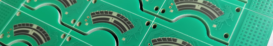
Rotary Potentiometer PCB
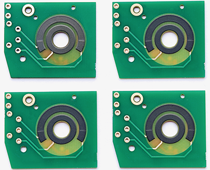
Rotary Potentiometer PCBs are custom-designed, specialized circuit boards that integrate variable resistors or sensors into printed circuit boards, optimizing component layout, saving space, and allowing users to directly mount rotary knobs or shafts to adjust resistance values, making them efficient for applications like volume control, position sensing, and frequency adjustments, which utilize thick film resistor technology with substrates such as PI, FR4, or ceramics, and undergo a manufacturing process involving sequential printing of conductive, resistive, and insulating materials, followed by high-temperature sintering and laser trimming to create circular resistor tracks. Rotary Potentiometer PCBs, also referred to as Rotary Potentiometer Sensor PCBs, function as voltage dividers where the resistor values can be measured at any position on the thick film resistive elements by using sliding wipers between applied voltage values. Once mounted with the housings, shafts, slider blocks, and bearings, they become complete rotary potentiometer PCBs. These types of PCBs are commonly utilized for controlling electrical devices like volume controls in audio equipment, dimmer switches for lights, and various applications requiring variable resistance. Rotary Potentiometer Sensor PCBs serve as platforms for mounting and connecting electronic components within circuits. By integrating the potentiometers onto the PCBs, they become easier to incorporate into electronic designs and provide more stable and reliable connections compared to manually wiring individual components together. Additionally, using Rotary Potentiometer PCBs effectively saves assembly space and provides product developers with various options. Most importantly, they help reduce manufacturing costs effectively. Functionality of Rotary Potentiometer PCB : |
 |
|
 |
1, Signal Control: The primary function of a rotary potentiometer PCB is to enable signal control. The potentiometer is a three-terminal device that acts as a variable resistor, allowing the adjustment of electrical signals passing through it, and incorporate the potentiometer into the overall system. 2, Voltage Dividers: Rotary potentiometers are often used as voltage dividers, dividing a voltage signal into a desired proportion. The PCB facilitates the connection of the potentiometer as part of a voltage divider circuit, allowing for precise control of the output voltage. 3, Circuit Protection: In some cases, the PCB may include circuit protection features such as surge protection, filtering, or noise reduction methods to enhance the reliability and longevity of the potentiometer and the overall circuit. |
|
4, Resistance Adjustment: The rotary potentiometer allows users to manually adjust the resistance value within a circuit. By rotating the potentiometer shaft, the resistance between its terminals changes, which can affect the output signal or voltage level in the connected circuit. The PCB ensures proper electrical contact and integration for this adjustment capability. 5, Analog Input/Output: With the ability to vary resistance, rotary potentiometers are commonly used as analog input or output devices in electronic systems. The PCB ensures the proper connection and integration of the potentiometer into the circuit, allowing for accurate analog signal processing. 6, User Interface: Rotary potentiometers are frequently used as user interface elements in various devices and systems. The PCB provides the necessary electrical connections and mechanical support for the potentiometer, allowing users to interact with the device by adjusting the resistance through the rotation of the potentiometer. The features of a rotary potentiometer PCB revolve around signal control, adjustment, voltage division, analog signal processing, user interaction, and circuit protection, depending on the specific application and design requirements. Please refer to Thick Film Potentiometer PCB for more informations. |
||
Advantages of Rotary Potentiometer PCB : |
Rotary Potentiometers, also known as rotary variable resistors or simply pots, are widely used in various electronic circuits and devices. When integrated into a PCB (Printed Circuit Board) as Rotary Potentiometer PCB, offer several advantages: 1, Customization: PCB-mounted potentiometers can be easily incorporated into the overall design of the circuit. They can be customized to match the specific requirements of the application, including resistance values, shaft lengths, and knob types. |
|
 |
2, Durability: PCB-mounted potentiometers are mechanically stable and less prone to damage or displacement compared to their panel-mounted counterparts. They are securely soldered onto the PCB, ensuring long-term reliability and resistance to vibrations and shocks. 3, Cost-effective: Integrating rotary potentiometers directly onto the PCB eliminates the need for additional connectors and wiring, resulting in cost savings during manufacturing. Furthermore, their mass production and availability make them relatively inexpensive components. 4, Precise control: Rotary potentiometers PCB provide smooth and continuous rotation, allowing for precise control over the output. This makes them ideal for applications that require accurate adjustment or calibration, such as volume control in audio devices or brightness control in lighting systems. 5, Compactness: PCB-mounted rotary potentiometers are designed to take up very little space on the board. They can be mounted directly onto the PCB, eliminating the need for additional wiring or external components. |
6, Integration with digital systems: Some PCB-mounted rotary potentiometers feature built-in digital encoders or switches. This allows for seamless integration with digital circuits and microcontrollers, enabling digital control and automation of the system. |
|
Applications of Rotary Potentiometer PCB : |
Rotary Potentiometers integrated into PCBs find applications in a wide range of electronic devices and systems. Here are some common applications: 1, Audio Equipment: Rotary potentiometer PCBs are extensively used in audio equipment such as amplifiers, mixers, and musical instruments. They are utilized for volume control, tone adjustment, balance control, and other audio parameter adjustments. 2, Industrial Controls: Rotary potentiometer PCBs are employed in industrial control systems for precise adjustment and calibration. They can be found in machine controls, robotics, process control equipment, and instrumentation devices. |
|
 |
3, Lighting Systems: Rotary potentiometers are used in lighting systems to control the brightness or intensity of lights. They are commonly found in dimmer switches, stage lighting controls, and automotive lighting systems. 4, Consumer Electronics: Many consumer electronic devices incorporate rotary potentiometers on PCBs. Some examples include televisions, radios, home appliances, gaming consoles, and portable audio players. They are used for various functions such as volume control, menu navigation, and user interface adjustments. 5, Automotive Applications: Rotary potentiometer PCBs play a role in automotive applications, particularly in the control panels and dashboards of vehicles. They are used for controlling features like air conditioning, fan speed, wiper speed, and headlight beam. 6, Robotics and Automation: Rotary potentiometer PCBs are employed in robotics and automation systems to provide position feedback and control. They are used in robotic arms, CNC machines, robotic vehicles, and other automated systems. |
7, Aerospace and Defense: Rotary potentiometer PCBs are utilized in aerospace and defense applications for their reliability and precision. They can be found in avionics systems, radar equipment, navigation systems, and communication devices onboard aircraft and spacecraft. 8, Medical Equipment: Rotary potentiometer PCBs find application in medical devices and equipment, including patient monitors, diagnostic instruments, and surgical tools. They are used for control and adjustment of various parameters in these devices. 9, Test and Measurement Instruments: Rotary potentiometers are utilized in test and measurement equipment such as oscilloscopes, signal generators, and multimeters. They enable precise adjustment of parameters and calibration in these devices. 10, Telecommunications: In telecommunications equipment, rotary potentiometer PCBs play a role in adjusting signal levels, frequency parameters, and other settings in devices such as radio transmitters, receivers, and base station equipment. They contribute to maintaining signal quality and optimizing communication networks. 11, Renewable Energy Systems: Rotary potentiometer PCBs are used in renewable energy systems such as solar power inverters and wind turbine controls. They enable precise adjustment of parameters related to power output, voltage regulation, and system monitoring, contributing to efficient energy conversion and management. |
|
Design Considerations for Rotary Potentiometer Sensor PCB : |
Design considerations for Rotary Potentiometer Sensor PCBs play a crucial role in ensuring optimal performance and functionality of the electronic device. Here is a professional introduction to the key design considerations: |
|
 |
1, Mechanical Compatibility: The PCB design should align with the mechanical dimensions and mounting requirements of the rotary potentiometer, ensuring proper fit and alignment within the overall system. 2, Electrical Layout: Careful consideration should be given to the electrical layout to minimize signal interference, noise, and crosstalk. Proper grounding and shielding techniques should be implemented to maintain signal integrity. 3, Resistance Tolerance and Linearity: Selecting potentiometers with appropriate resistance tolerance and linearity specifications is essential for accurate signal control and adjustment. The PCB design should accommodate these specifications for optimal performance. 4, Environmental Factors: Consider environmental factors such as temperature, humidity, and vibration to ensure the PCB design can withstand varying conditions without affecting performance or reliability. |
5, Interface Compatibility: Ensure that the PCB design is compatible with the interface requirements of the rotary potentiometer and other components in the system to facilitate seamless integration and operation. 6, Durability and Reliability: Design the Rotary Potentiometer Sensor PCB with robust materials and construction to enhance durability and reliability, especially in applications subject to mechanical stress or frequent use. |
|
How Does Rotary Potentiometer PCB Work ? |
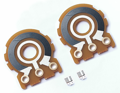
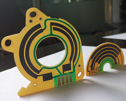
● Rotary Potentiometer PCB operates by utilizing a strip of carbon resistive material that maintains a constant density all around its circumference. As the control shaft rotates, the resistance between the center terminal and either end terminal changes at a consistent rate. The resistance between the middle terminal and either end terminal corresponds to a linear function of the angular position of the shaft. In most variable resistors, this relationship is linear, meaning that the relative position is proportional to the resistance ratio. This type of potentiometer features two terminal contacts arranged in a semi-circular pattern, creating a uniform resistance distribution. Additionally, it includes a middle terminal connected to the resistance via a sliding wiper, which is controlled by a rotating knob. By turning the knob and moving the sliding wiper along the half-circular resistance track, the voltage can be obtained across the two resistance contacts and the sliding wiper. These rotary potentiometer PCBs are commonly employed in applications requiring precise voltage control. |
|
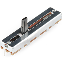
● Linear Potentiometer PCB operates by incorporating a resistive element on the PCB itself. The two end terminals are connected to a thick film resistor, while the wiper travels along the resistor strip when the knob is moved. The resistance value varies depending on the position of the multi-wire wiper relative to the end terminal it is wired with. When the wiper is closer to the terminal, the resistance decreases because the current path becomes shorter. Conversely, as the wiper moves away from the terminal, the resistance increases. For instance, when the sliding contact is at the middle position, the variable resistance value is half of the full-scale resistance of the potentiometer. In this type of potentiometer, the multi-wire wiper moves along a linear path, often referred to as a slide pot, slider, or fader. It shares similarities with the rotary potentiometer, but in the linear potentiometer, the sliding wiper moves along the resistor in a linear fashion. The two terminals of the resistor are connected across the voltage source, and the sliding wiper can be adjusted along the resistor's path to control the voltage output. |
|
Types of Rotary Potentiometer PCB : |
 |
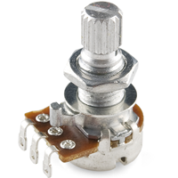
Rotary Potentiometers PCBs are the most common types of potentiometers used. They consist of an adjustable wiper that moves in a circular motion when turning the knob, The thick film resistive material is printed in a semi-circular pattern between the two terminals, They are primarily used to obtain an adjustable supply of voltage. 1, Servo Potentiometers : consist of motorized potentiometers that can automatically adjust the voltage supplied. 2, Single-Turn potentiometer : only rotate three-fourths of a complete turn (270°). 3, Concentric Potentiometers : consist of two potentiometers connected individually to the shaft. 4, Dual-Gang Potentiometers : consists of two potentiometers connected on the same shaft. They allow controlling two different channels simultaneously. 5, Multi-Turn Potentiometers : provide multiple rotations and are more precise. Please check more details as following : |
Type |
Description |
Applications |
Single-turn pot |
Single rotation of approximately 270 degrees or 3/4 of a full turn. |
Most common pot, used in applications where a single turn provides enough control resolution. |
Multi-turn pot |
Multiple rotations (mostly 5, 10 or 20), for increased precision. They are constructed either with a wiper that follows a spiral or helix form, or by using a worm-gear. |
Used where high precision and resolution is required. The worm-gear multi turn pots are often used as trimpots on PCB. |
Dual-gang pot |
Two potentiometer combined on the same shaft, enabling the parallel setting of two channels. Most common are single turn potentiometers with equal resistance and taper. More than two gangs are possible but not very common. |
Used in for example stereo audio volume control or other applications where 2 channels have to be adjusted in parallel. |
Concentric pot |
Dual potmeter, where the two potentiometers are individually adjusted by means of concentric shafts. Enables the use of two controls on one unit. |
Often encountered in (older) car radios, where the volume and tone controls are combined. |
Servo pot |
A motorized potmeter which can also be automatically adjusted by a servo motor. |
Used where manual and automatic adjustment is required. Often seen in audio equipment, where the remote-control can turn the volume control knob. |
Linearity Definition of Rotary Potentiometer PCB : |
1, Linearity of a rotary potentiometer PCB refers to its ability to provide an output signal that is directly proportional to the position of the rotary shaft. It determines how accurately the potentiometer can measure and reproduce changes in rotational position. 2, A rotary potentiometer PCB is designed to produce a linear relationship between the physical position of the shaft and the electrical output signal. This means that as the shaft rotates, the resistance value changes linearly, resulting in a linear change in voltage or current across the potentiometer. 3, Linearity is an important characteristic for applications where precise and accurate position sensing is required. It ensures that the potentiometer provides a consistent and predictable response to changes in position, making it suitable for applications such as volume control, position control, and user interface input devices. |
 |
4, The typically specify the linearity of a potentiometer as a percentage of the maximum deviation from a perfectly linear response. For example, a potentiometer with a linearity specification of ±1% means that the actual output may deviate from a perfect linear relationship by up to 1% of the full-scale range. 5, Linearity is the deviation of the output characteristic curve as compared to an ideal straight line. It is measured by the greatest deviation from the ideal straight line with respect to the applied voltage. The deviation is given in %. Essentially three types of nonlinearities can be provided for potentiometer sensor specifications: ● Independent Linearity: This type of linearity considers the deviation of the output characteristic curve independently, without reference to any other variables or conditions. ● Absolute Linearity: Absolute linearity takes into account the overall deviation of the output characteristic curve, considering all possible factors and conditions. ● Terminal Linearity: Terminal linearity focuses on the deviation of the output characteristic curve at the ends or terminals of the sensor's measurement range. 6, The required type of linearity and linearity deviation should always be customized for the each specific application, For example can be 0.25% or 0.5% by laser trimming process, Specifying a percentage of linearity - without further information - automatically implies independent. |
|
What's Important Role of Linearity in Rotary Potentiometer PCB ? |
The linearity of a rotary potentiometer in the context of PCB design plays a crucial role in ensuring accurate and predictable electrical response throughout its range of motion. Linearity refers to the relationship between the physical position of the potentiometer's wiper and the resulting electrical output. In rotary potentiometer PCBs, the importance of linearity can be understood through several key aspects: 1, Signal Accuracy: Linearity directly impacts the accuracy of the output signal corresponding to the rotational position of the potentiometer. A high degree of linearity ensures that the electrical output faithfully represents the mechanical input, facilitating precise control and measurement in electronic circuits. |
|
 |
2, Control System Performance: In applications where rotary potentiometers are used for control purposes, such as in audio equipment or industrial instrumentation, linearity is essential for maintaining consistent and proportional response to user inputs. Deviations from linear behavior can lead to non-uniform control characteristics and affect system performance. 3, Calibration and Sensitivity: Linearity influences the ease and effectiveness of calibration procedures for rotary potentiometer PCBs. A linear response simplifies calibration processes and ensures that small adjustments to the potentiometer's position result in proportional changes to the output signal, enhancing sensitivity and fine-tuning capabilities. 4, System Compatibility: When integrating rotary potentiometer PCBs into larger electronic systems, linearity becomes critical for compatibility with downstream components, analog-to-digital converters, or signal processing circuits. Maintaining linearity helps to minimize signal distortion and interface seamlessly. |
5, Measurement and Feedback: In applications where rotary potentiometers are used for position sensing or feedback control, linearity is fundamental for accurately capturing and interpreting positional data. Consistent linearity supports reliable measurement and feedback mechanisms within the PCB design. |
|
Enhancing Durability For Rotary Potentiometer Sensor PCB : |
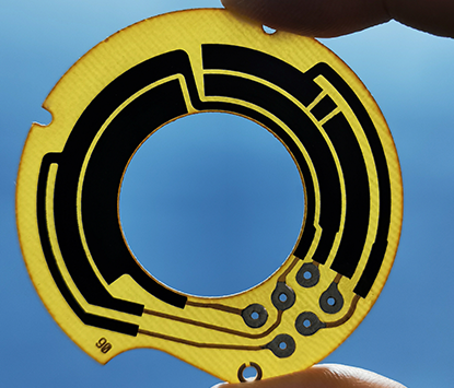
The durability of carbon film is crucial for Rotary Potentiometer Sensor PCBs due to its impact on the overall performance and longevity of the potentiometer. Carbon film, as a common material used in potentiometers, serves as the resistive element that directly affects the accuracy and reliability of the device. Enhancing the durability of carbon film can be achieved through various methods, such as: 1, Polishing and Grinding: By carefully polishing and grinding the carbon film surface, any uneven or rough areas can be smoothed out, reducing the risk of premature wear and ensuring consistent electrical contact. |
|
 |
2, Optimizing Manufacturing Processes: Ensuring proper manufacturing processes, including precise printing of carbon film and quality control measures, can significantly improve the durability of the film. 3, Temperature and Humidity Control: Maintaining stable temperature and humidity conditions during operation and storage can prevent the carbon film from deteriorating due to environmental stressors. 4, Optimal PCB Layout: Organize the layout to facilitate signal flow and minimize the length of interconnections. Keep components related to a function grouped together. 5, Thermal Management: Ensure that heat-generating components are spaced appropriately from temperature-sensitive components to prevent thermal degradation. 6, Use of Robust Components: Select components that are designed for durability and long-term reliability, especially for parts that are subject to mechanical stress. 7, Adaptation to Mechanical Stress: Design the potentiometer's mounting and engagement mechanism to withstand the mechanical stress induced during operation. |
8, Quality of Materials: Use high-quality materials for both the potentiometer and the PCB to ensure that they can withstand physical wear and environmental factors over time. 9, Testing and Validation: Conduct thorough testing and validation of the Rotary Potentiometer Sensor PCB design to ensure that it meets durability and performance standards before going into production. |
|
Multi-Wire Wipers Used For Rotary Potentiometer PCB : |
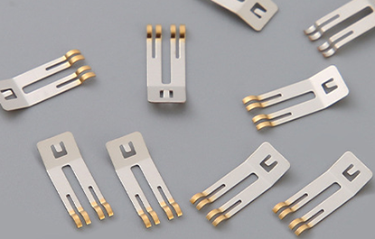 |
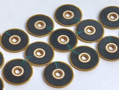
Multi-Wire Wipers are crucial components designed to transmit voltage and signals. They perform linear or rotational sliding over the surfaces of resistive materials (thick film resistors) to adjust resistance values and act as contact elements in voltage dividers. Wiper design significantly impacts the efficiency and lifespan of the sensor assembly. When designing the wiper, it is essential to consider factors such as contact resistance, operating load, repeatability, hysteresis, the resistive material used, as well as the wiper material, its shape, and the applied wiper pressure. We also offer custom Multi-Wire Wipers (contact) tailored to the specific needs of our customers. We can manufacture wipers according to the customer's design requirements or specifications. For more information about our wipers, please refer to our section on Multi-Contact Wipers. |
Engineering Specification of Rotary Potentiometer PCB : |
Items : |
Typical Values |
Advanced Capabilities |
1, Substrates : |
FR4, Ceramic ( AI203, ALN, BeO, ZrO2), Polyimide (Flexible PI), Stainless Steel (SUS304), Mica |
FR4, Ceramic ( AI203, ALN, BeO, ZrO2), Polyimide (Flexible PI), Stainless Steel (SUS304), Mica |
2, Conductor (Paste) Materials : |
Copper, Silver , Gold , Silver-Palladium, Palladium-Gold, Platinum-Silver, Platinum-Gold |
Copper, Silver , Gold , Silver-Palladium, Palladium-Gold, Platinum-Silver, Platinum-Gold |
3, Thick Film Carbon Thickness (Height) : |
15um +/-5 um |
30um +/-5 um |
4, Conductor Thickness (Height) : |
12um+/-5um |
20um+/-5um |
5, Min Width of Thick Film Line : |
0.30 mm +/-0.05 mm |
0.20 mm +/-0.05 mm |
6, Min Space of Thick Film Line : |
0.30 mm +/-0.05 mm |
0.20 mm +/-0.05 mm |
7, Min Overlap (Carbon to Conductor) : |
No less than 0.25mm |
0.20mm (Minimum) |
8, Sheet Resistivity (ohms/square): |
Printed resistors in milli ohm to mega ohm range (Customizable) with tolerances of 1-10% are fabricated and protected with overglaze materials |
Printed resistors in milli ohm to mega ohm range (Customizable) with tolerances of 0.5-10% are fabricated and protected with overglaze materials |
9, Resistor Value Tolerance (ohms) : |
+/-10.0% (Standard) (Customizable) |
+/-0.5% (Laser trimming) |
10, Linearity : |
+/-1.0% (Standard) (Customizable) |
+/-0.2 ~ +/-0.5% (Laser trimming) |
11, Synchronism of Double Channels : |
+/-2.0% (Standard) (Customizable) (Potentiometers) |
+/-1.0% (Laser trimming) (Potentiometers) |
12, Durability of Carbon Ink (Life time) : |
0.5 Million (Min), 2.0 Million (Standard) |
5.0-10.0 Million (Max) with Surface Polishing |
13, Working Temperature : |
- 40ºC /+150ºC |
- 40ºC /+180ºC |