Flexible PCB
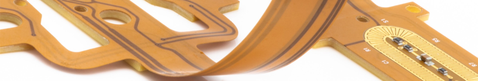
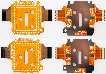
Flexible PCBs, also known as Flex PCBs, are electronic circuit boards made from flexible substrates such as polyimide or polyester, differing from traditional rigid PCBs in structure and materials, and their unique design allows them to bend and fold, providing versatility in applications where space, compactness, and flexibility are crucial, with their core function being to offer electrical connections between components in a flexible, lightweight format, enabling electronic systems to operate efficiently even in confined or complex spaces. Flexible PCBs offer significant advantages over traditional rigid boards due to their flexibility, space-saving capabilities, and lightweight design. They allow for a more compact arrangement of electronic components, as they can be bent and shaped to fit into smaller or non-traditional spaces. This flexibility enhances reliability by reducing the number of interconnections and solder joints, thus lowering the risk of failure due to mechanical stress. Additionally, flexible PCBs are highly durable, capable of withstanding higher levels of vibration and thermal stress compared to rigid counterparts, making them ideal for use in demanding environments. Flex PCBs are widely used in industries that require compact, high-performance circuitry, particularly where space constraints and flexibility are paramount. They find applications in consumer electronics such as smartphones, tablets, and cameras, where compactness is crucial without sacrificing functionality. Other significant sectors include automotive, aerospace, and medical devices. In automotive systems, for instance, flexible PCBs are used in sensors and control systems, while in medical applications, they are integrated into devices like pacemakers and implants. Wearable technology, such as fitness trackers and smartwatches, also heavily relies on the versatility of Flex PCBs to maintain a lightweight and durable design. Main Features of Flexible PCB : |
 |
|
 |
1, Flexibility: The most obvious feature of flexible PCBs is their flexibility. Unlike rigid PCBs, flexible PCBs can bend, twist, and fold without compromising their functionality. This flexibility allows them to be easily integrated into devices with curved or irregular shapes. 2, Space-saving: Flexible PCBs are thinner and lighter than traditional rigid PCBs, making them ideal for applications where space is limited. Their compact design allows for more efficient use of available space within a device. 3, High reliability: Flexible PCBs are less prone to mechanical stress and vibration damage compared to rigid PCBs. The absence of solder joints in flexible PCBs reduces the risk of failure due to mechanical fatigue. |
|
4, Improved signal integrity: The flexibility of the substrate material used in flexible PCBs can help reduce signal loss and impedance mismatch, leading to improved signal integrity and better electrical performance. 5, Higher component density: Flexible PCBs support higher component density and miniaturization due to their ability to bend and fold, allowing for more compact designs and integration of additional components. 6, Cost-effective: While the initial manufacturing cost of flexible PCBs may be higher than rigid PCBs, the overall cost savings can be significant due to reduced assembly time, lower material costs, and simplified installation processes. 7, Resistance to environmental factors: Flexible PCBs are often more resistant to environmental factors such as moisture, heat, and chemicals, making them suitable for use in harsh operating conditions. 8, Design versatility: Flexible PCBs offer greater design freedom compared to rigid PCBs, allowing for innovative and unconventional shapes and configurations in electronic devices. Flexible PCBs offer key features such as flexibility, space-saving design, high reliability, improved signal integrity, higher component density, cost-effectiveness, resistance to environmental factors, and design versatility. These advantages make flexible PCBs an ideal choice for various applications across multiple industries. If you are looking for a flexible PCB or rigid-flex PCB supplier, our experts are here to assist you in maximizing the value for your business. |
||
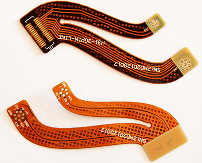
Stackups of Flexible PCB : |
Flexible PCBs have a stackup that refers to the arrangement and layering of various materials and conductive layers that form the structure of the PCB. The specific stackup configuration can vary based on the application requirements and desired performance characteristics. Below are some common stackup configurations for flexible PCBs: 1, Single-sided stackup: This is the simplest stackup configuration, consisting of a single layer of flexible substrate material with conductive traces and components on one side. This configuration is commonly used for simple and low-density applications. |
|
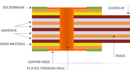 |
2, Double-sided stackup: In this configuration, there are two layers of flexible substrate material, with conductive traces and components on both sides. The layers are typically interconnected using vias or through-hole plating. Double-sided stackups allow for increased component density and more complex circuit designs. 3, Multilayer stackup: Multilayer flexible PCBs consist of three or more layers of flexible substrate material with conductive traces and components on each layer. The layers are separated by insulating layers, known as prepreg, and are interconnected using vias or microvias. Multilayer stackups provide even higher component density and more complex routing capabilities. |
4, Stiffeners: In addition to the substrate and conductive layers, the stackup may also include other layers such as solder mask, coverlay, and stiffeners. These layers provide protection, insulation, and mechanical support to the flexible PCB. 5, Rigid-flex stackup: Rigid-flex PCBs combine both rigid and flexible sections in their stackup. The rigid sections are made of traditional rigid PCB materials, while the flexible sections consist of flexible substrate material. This stackup configuration allows for the combination of the benefits of both rigid and flexible PCBs, making it suitable for applications that require a mix of flexibility and rigidity. It's important to note that the specific stackup configuration will depend on factors such as the required electrical performance, mechanical flexibility, thermal management, and manufacturing constraints. |
|
Main Applications of Flexible PCB : |
1, Automotive Industry: Flexible PCBs enhance the automotive industry by increasing reliability and contributing to weight reduction, which is crucial for fuel efficiency. Their resistance to vibrations makes them suitable for demanding environments, improving performance in GPS systems, engine controls, airbag systems, and anti-lock braking systems. This technology streamlines vehicle manufacturing processes, reducing labor costs. 2, Industrial Sector: In the realm of industrial applications, Flexible PCBs are pivotal in facilitating advancements in radio frequency communication, power circuits, and industrial automation. Their adaptability under stressful conditions and contribution to design flexibility open new avenues for innovative industrial solutions. |
|
 |
3, Military Applications: The military demands uncompromising quality and precision in PCB designs, necessitating rigorous quality checks at every stage from fabrication to deployment. Flexible PCBs meet these high standards, ensuring reliability and performance in critical military technologies. 4, Aerospace: In aerospace, Flexible PCBs bolster the reliability of equipment and enable more versatile design possibilities. Their applications extend to radio frequency communications, power distribution, and control circuits. Their advantage over rigid boards lies in enabling sensors to be significantly smaller and thinner, enhancing aerospace technology. 5, Power Electronics: The inherent flexibility and thinness of copper in Flexible PCBs allow for efficient handling of heavy power currents, a critical factor in power electronics where devices demand substantial power for optimal operation. |
6, Medical Field: Flexible PCBs are increasingly vital in medical devices such as pacemakers, hearing aids, exercise monitors, and heart monitors. The evolution of healthcare technology has expanded their use, making them indispensable for applications requiring circuits to endure extreme bodily conditions. 7, Consumer Electronics: The versatility of Flexible PCBs is evident in their widespread application across various consumer electronics, including laptops, cameras, flip cell phones, and calculators. Their flexibility and compactness support the development of sleek, innovative designs. 8, Communication Electronics: Reliability is paramount in communication technology, and Flexible PCBs excel in managing the complex architectures of mobile phones and other devices. They are integral to the functionality of satellites, signal processing equipment, servers, media transmission systems, and wireless communications, ensuring seamless connectivity and robust performance. Flexible PCBs are transforming a wide range of industries by offering unparalleled design flexibility, reliability, and efficiency. Their role in advancing technology across automotive, industrial, military, aerospace, power electronics, medical, consumer, and communication electronics underscores their significance in the modern technological landscape. |
|
Advantages of Flexible Printed Circuit Boards : |
1, Precision in Design: Flexible Printed Circuit Boards are manufactured and assembled using automated machinery, which minimizes human error and ensures high precision a critical factor for the functionality of electronic devices. 2, Exceptional High-Temperature Performance: The use of Polyimide (PI) material allows Flexible PCBs to operate effectively in high-temperature environments, making them suitable for applications that require heat resistance. 3, Enhanced Airflow and Heat Dissipation: Designed to improve heat dissipation, Flexible Printed Circuit Boards facilitate better airflow, which helps keep circuits on FR4 boards cooler and enhances the overall performance and longevity of electronic circuit boards. |
|
 |
4, Design Freedom: The ability to add multiple layers to Flexible PCBs grants designers significant freedom. These PCBs can be crafted in various configurations, including single-sided, double-sided, and multilayered designs, with the possibility of incorporating plated-through holes and surface-mounted components. 5, Enhanced Durability and Manufacturability: The lower toughness of Flexible PCBs makes them more resistant to thermal stress, significantly reducing the risk of joint cracking. Additionally, the use of flexible materials allows for the creation of pads or windows through laser or chemical etching, facilitating double access applications. 6, Superior Flexibility: The stable and repeatable flexibility of Flexible PCBs is crucial for assembling 3D electronic products. These PCBs can connect across multiple planes, minimizing the space and weight constraints associated with traditional circuit boards. Moreover, they can be flexed to various degrees during installation without causing damage, offering unparalleled adaptability. |
7, Increased System Reliability: Modern Flexible PCBs have fewer interconnections, reducing the potential for failure due to interconnection issues. The use of polyimide material further enhances thermal stability, making these PCBs more reliable under demanding conditions. 8, Cost Efficiency: The thin and flexible nature of polyimide films lowers assembly costs by allowing for integration into compact spaces. Flexible PCBs also lead to reductions in testing time, routing errors, rejections, and rework time, thereby offering superior performance during testing phases. 9, Thin Dielectric for Improved Performance: The thin dielectric layer of Flexible PCBs offers better flexibility and heat transfer capabilities, benefiting structural design and thermal management. This feature enables the integration of rigid-flex technology, reducing the need for connectors and terminators and consequently decreasing weight. 10, Optimized Space Utilization: By replacing numerous connecting parts and bridging multi-plane boards, Flexible PCBs excel in saving space and simplifying design processes. Their thin, lightweight nature allows for placement in areas inaccessible to other components. Moreover, rigid-flex engineers often employ 3D packaging geometries to further minimize package size. Flexible PCBs offer a myriad of advantages, including improved durability, precision, design flexibility, and cost efficiency. Their unique properties make them indispensable in modern electronics design, catering to a wide range of applications from consumer electronics to aerospace and medical devices. |
|
Introduction to Materials Used in Flexible PCB : |
1, Substrate and Coverlay Films: In most flexible PCB applications, a more flexible plastic material than the standard network epoxy resin is required. The primary choice for a flex PCB substrate is polyimide, also known as "PI" substrate. This material is highly flexible, durable, and heat-resistant. Polyimide films, along with thin flexible-epoxy-and-glass-fiber cores, are commonly used as substrates for flex circuits. |
|
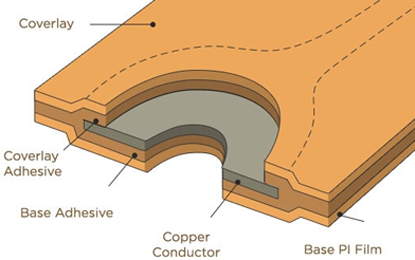 |
Coverlay insulation, typically made of PI or PET, serves as the outer surface that insulates conductors and protects them from corrosion and damage, similar to how solder mask functions on rigid boards. Additional films, such as flexible solder mask ink, may be used for coverlay. PI and PET film thicknesses range from ⅓ mil to 3 mils, with 1 or 2 mils being standard. 2, Conductors: When using the flexible part of the circuit to streamline manufacturing and reduce costs by eliminating cabling and connectors, Electro-Deposited copper can serve as the conductor, similar to laminated copper foil used in rigid boards. For applications involving repeated creasing or movement of the flexible PCB, higher-grade Rolled Annealed foils should be considered. Annealed copper allows for more stretching before fatigue cracking, making it ideal for flexible PCBs subject to bending. |
3, Adhesives: PCB manufacturers offer pre-laminated single- and double-sided copper-clad films for etching flexible PCBs, using acrylic or epoxy-based adhesives with typical thicknesses of ½ and 1 mil. These adhesives are designed for flexibility. Adhesives play a crucial role in bonding the copper foil to PI (or other) films in flexible PCBs, as the annealed copper lacks the roughness required for a reliable bond compared to typical FR-4 PCBs. "Adhesiveless" laminates, also known as "No flow prepreg," are increasingly used due to newer processes involving direct copper plating or deposition onto polyimide film. These films are selected for applications requiring finer pitches and smaller vias, such as HDI circuits. Additionally, special materials like silicones, hot-melt glues, and epoxy resins are utilized for adding protective beads to flex-to-rigid joints or interfaces, providing mechanical reinforcement to prevent fatigue cracking or tearing during repeated use. |
|
Design Considerations of Flexible Printed Circuit Board : |
1, Pad Fillets: Incorporating pad fillets in the design of a Flexible Printed Circuit Board can enhance etched yield and material strength, especially when the pad diameter exceeds the connecting strand width. The design should also consider the pad's location to ensure that it does not interfere with other components or signal traces. 2, Tear Relief: To prevent tears in a Flexible Printed Circuit Board, options like relief slots and large corner radii can be employed effectively. The size and location of these features should be carefully considered to avoid interference with components or signal traces. |
|
 |
3, Bend Ratio: The bend ratio relates the bend radius to the thickness of the flexible PCB. Higher chances of failure during flexing occur with tighter bend radii. Hence, it is essential to review the bend radius and thickness to ensure that the flexible PCB can withstand the intended level of flexing. 4, Conductors and Routing: Careful consideration must be given to conductor routing for transmitting electrical current effectively. Analyzing the conductor pattern's susceptibility to flexing is crucial. Conductors of the flex part should always be routed through bend areas as perpendicular as possible to minimize stress on the conductors. 5, Stiffeners: Mechanical stiffeners can reinforce the SMT process, connectors, and other vulnerable areas on the flexible PCB. The design should consider the location and size of the stiffeners to avoid interfering with other components or signal traces. |
6, Surface Mounting-Access Openings: Designing Flexible Printed Circuit Boards with specific areas for surface mount components is essential. Coverlays finished by laser trimming or photo-imageable materials can create intricate openings for dense surface mount patterns. The design should also consider the components' placement to ensure that they are not affected by flexing. 7, Plane Layers and Shielding: Reference plane layers and shielding play a vital role in impedance control and signal integrity. Solid copper shielding enhances circuit rigidity and should be factored into the thickness-to-bend radius assessment. Other shielding methods, such as conductive foils or films, can also be used to increase flexibility while maintaining signal integrity. 8, Assembly Considerations: Prior to subjecting the circuit to high temperatures, ensure complete removal of moisture. Immediate processing post-baking is recommended. If immediate processing is not feasible, store the flexible PCB in a nitrogen chamber or sealed dry box with desiccant. The design should also consider the ease of assembly and manufacturing processes. 9, Controlled Impedance and Signal Integrity: Controlled impedance dictates how electricity travels down a trace. Matching impedance ensures proper signal functionality and overall circuit board performance. Factors influencing impedance characteristics include the insulation substrate's relative permittivity, copper trace width, distance from reference plane layers, trace copper thickness, and spacing between trace signals in different applications. The design should consider these factors to ensure optimal impedance control and signal integrity. |
|
Differences Between Flexible PCB and Rigid PCB : |
1, Materials: 2, Flexibility: 3, Size and Weight: |
|
 |
4, Durability: 5, Cost: 6, Design Complexity: |
7, Installation and Assembly: 8, Applications: |
|
Manufacturing Processes of Flexible PCB : |
Flexible PCBs involve several key manufacturing processes to ensure the production of high-quality and reliable flexible circuits. Below is an overview of the typical manufacturing processes involved in producing flexible PCBs: 1, Design and Layout: 2, Material Selection: 3, Preparation of Base Material: |
|
 |
4, Lamination: 5, Drilling: 6, Copper Plating: 7, Etching: |
8, Surface Finish: 9, Testing and Inspection: 10, Final Fabrication: |
|
Why Choose PANDA PCB for Your Flexible PCB ? |
1, Expertise: With years of experience in the industry, PANDA PCB is a trusted name known for delivering high-quality flexible PCBs tailored to your unique requirements. 2, Cutting-Edge Technology: We utilize state-of-the-art manufacturing processes and advanced technology to ensure precision, reliability, and performance in every flexible PCB we produce. |
|
 |
3, Customization: At PANDA PCB, we understand that one size does not fit all. Our team works closely with you to customize flexible PCB designs that meet your specific needs and applications. 4, Quality Assurance: Quality is our top priority. Each flexible PCB undergoes rigorous testing and inspection to guarantee superior quality, consistency, and durability. 5, Timely Delivery: We value your time. PANDA PCB is committed to delivering your flexible PCB orders promptly, ensuring you meet your project deadlines without any delays. 6, Cost-Effective Solutions: Get top-notch flexible PCBs at competitive prices. PANDA PCB offers cost-effective solutions without compromising on quality or performance. |
7, Customer Satisfaction: Your satisfaction is our success. Our dedicated customer support team is always ready to assist you, providing personalized service and support throughout your project. Choose PANDA PCB Group for your flexible PCB needs and experience excellence in every circuit. Contact us today to discuss your requirements and discover why we are the preferred choice for flexible PCB solutions! |
|
Engineering Specification of Flexible PCB : |
Items |
Description |
Production Capabilities |
Materials
|
Flex raw material(with adhensive) |
ShengYi SF302: PI=0.5mil, 1mil, 2mil, Cu=0.5oz, 1oz Panasonic RF-775/777 : PI=1mil, 2mil, 3mil, Cu=0.5oz,1oz Thinflex: PI=1mil, 2mil, Cu=0.33oz, 0.5oz, 1oz |
Cover film |
ShengYi SF302C: 0515, 0525, 1025, 2030 Thinflex: 0510, 1010 TaiHong FHK: 1025, 1035 |
|
Pure adhensive |
TaiHong : AD=10um, 25um, 40um ShengYi SF302B: AD=25um, 40um TaiHong MHK : PI=3mil, 5mil , 7mil, 9mil |
|
3M tape |
9077, 6677, 9458 |
|
PI Stiffener |
TaiHong MHK : PI=3mil, 5mil , 7mil, 9mil |
|
Normal rigid board material |
IT-180A, S1141, S1000-2 |
|
Special rigid board material |
Arlon: 85N, Rogers: RO4000, Nelco: N4000-13, Ventec: VT-901 |
|
Special Capabilities |
Layer count (flex layer) |
2-12 layers |
Finished board thickness |
0.5mm-3.0mm (rigid) |
|
Board thickness tolerance(>1.0mm) |
board thickness ±10% |
|
Impedance control tolerance |
Singal end: ±5Ω(≤50Ω), ±10%(>50Ω), DIFF: ±5Ω(≤50Ω), ±10%(>50Ω) |
|
Bow and twist(min.) |
0.75%(symmetry), 2%(asymmetry) |
|
Min. distance from conductor to combine place for flex&rigid |
0.5mm(through slot/half slot technolgy) |
|
Suface finish |
OSP, HAL/LF HAL,ENIG, ENPIG, Plating nickel gold copper, Plating soft gold, Plating hard gold, Immerison silver, Immersion Tin |
|
Max panel size |
220mm×400mm |