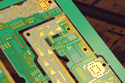
Rogers PCB
Rogers PCBs are high-performance printed circuit boards made with Rogers Corporation's specialized high-frequency laminates, renowned for their exceptional electrical properties, including low dielectric loss, stable performance at high frequencies, and superior thermal conductivity, making them perfect for applications where reliability, signal integrity, and thermal management are critical, such as telecommunications and advanced electronics, ensuring the consistent and efficient operation of electronic devices in demanding environments. Rogers PCBs also called Rogers Material PCBs, are widely used in wireless communications, wireless networks and satellite communications, in particular the popularity of 3G-10G networks exacerbate the market demand for the product on the Rogers High Frequency PCB. Today, The demand for Rogers High Frequency PCB design is on the rise, Access to wireless high speed data is quickly becoming a necessity in multiple markets like Defense, Aerospace and Mobile Networks. Evolving market needs continue to drive forward development of high frequency PCB, For example 50+ GHz microwave radios or defense airborne systems. Rogers Material PCBs, through its Advanced Connectivity Solutions (ACS) business, provide leading circuit material solutions, including high-frequency laminates, bondplys, and prepregs, engineered to meet stringent performance requirements, and with exceptional dielectric constant control, Rogers Material PCBs are a consistent and reliable choice for applications in 5G wireless communication, automotive radar sensors, aerospace, satellites, and more. Main Material Features of Rogers PCB : |
 |
|
 |
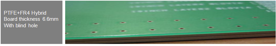
● Low Dielectric constant(2.40) with tight tolerance. PTFE PCB and Ceramic PCB filled composite. |
|
Advantages of Rogers PCB : |
1, Signal Integrity: Rogers PCBs help maintain signal integrity by minimizing signal loss and impedance variations, making them ideal for high-speed digital and RF designs where maintaining signal quality is crucial. |
|
 |
2, High Frequency Performance: Rogers PCBs are well-suited for high-frequency applications due to their low dielectric loss and stable electrical characteristics, allowing for reliable signal transmission without significant attenuation or distortion. 3, Chemical Resistance: Rogers PCBs exhibit resistance to chemicals, enhancing their durability and suitability for use in harsh or demanding environments. 4, Dimensional Stability: Rogers PCBs offer excellent dimensional stability, ensuring that the board's shape and size remain consistent even in varying environmental conditions, contributing to the reliability of electronic assemblies. 5, Thermal Management: With high thermal conductivity, Rogers PCBs effectively dissipate heat, making them suitable for high-power applications and devices requiring efficient thermal management. |
6, Design Flexibility: These PCBs can be designed with various layer counts, stackups, and configurations, providing flexibility to accommodate diverse design requirements. 7, Reliability: The consistent electrical and mechanical properties of Rogers PCBs contribute to the overall reliability and longevity of electronic products and systems. Rogers PCBs, with their unique material properties and performance characteristics such as low dielectric loss, excellent high-frequency stability, and superior thermal conductivity, are a preferred choice for applications that demand exceptional performance, signal integrity, and long-term reliability, even in the most challenging operating conditions like extreme temperatures, high vibrations, and complex electromagnetic environments, making them indispensable in industries such as telecommunications, aerospace, automotive, and medical devices. |
|
Typical Applications of Rogers PCB : |
Rogers PCBs find application in various industries and technologies that require high-frequency performance, signal integrity, and thermal management. Some typical applications of Rogers PCB include: 1, RF/Microwave Applications: Rogers PCBs are extensively utilized in RF and microwave applications such as radio frequency identification (RFID) systems, microwave antennas, transceivers, and radar systems. Their low dielectric loss and stable electrical characteristics make them well-suited for these applications. 2, Aerospace and Defense: In aerospace and defense applications, Rogers PCBs are utilized in radar systems, avionics, satellite communication systems, and navigation equipment. Their high-frequency capabilities, thermal management properties, and reliability make them suitable for critical applications in these industries. |
|
 |
3, High-Speed Digital Designs: Rogers PCBs are used in high-speed digital designs, including computer servers, network switches, routers, and data storage systems. These PCBs offer low signal loss, controlled impedance, and minimal crosstalk, ensuring signal integrity and high-speed data transmission. 4, Wireless Communication: Rogers PCBs are widely used in wireless communication systems such as cellular networks, Wi-Fi devices, Bluetooth modules, and satellite communication systems. These PCBs enable reliable signal transmission, minimize signal loss, and maintain optimal performance at high frequencies. 5, Power Electronics: Rogers PCBs are employed in power electronics applications, including power amplifiers, power supplies, inverters, and motor control systems. The high thermal conductivity of these PCBs helps dissipate heat effectively, ensuring optimal performance and reliability of power electronic devices. |
6, Automotive Electronics: Rogers PCBs are employed in automotive electronics, particularly in radar-based driver assistance systems, collision avoidance systems, and vehicle communication networks. The high-frequency performance and thermal management characteristics of these PCBs ensure accurate and reliable operation in demanding automotive environments. 7, Medical Devices: Rogers PCBs are used in medical devices and equipment, such as diagnostic imaging systems, patient monitoring systems, and medical telemetry devices. These PCBs provide reliable signal transmission, high-frequency performance, and thermal management capabilities necessary for medical applications. These are just a few examples of the wide range of applications where Rogers PCBs excel, thanks to their unique material properties, such as low dielectric loss, high-frequency stability, and superior thermal conductivity, which enable reliable and high-performance operation in demanding environments across industries like telecommunications, aerospace, automotive, and medical devices. |
|
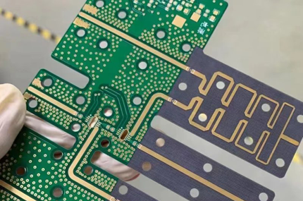
Special Processes of Rogers Material PCB : |
Rogers Material PCBs may involve several special processes to ensure optimal performance and reliability. Some of these special processes include: 1, High-Precision Drilling: High-precision drilling is crucial for Rogers Material PCBs, especially when it comes to vias and plated-through holes. Precise drilling techniques ensure accurate alignment and proper connection between different layers of the PCB, maintaining the integrity of the circuitry. 2, Surface Finish Options: Rogers Material PCBs may undergo specific surface finish processes based on the application requirements. Common surface finish options include HASL (Hot Air Solder Leveling), ENIG (Electroless Nickel Immersion Gold), OSP (Organic Solderability Preservative), and immersion tin or silver finishes. The choice of surface finish depends on factors such as solderability, corrosion resistance, and electrical performance. |
|
 |
3, Microstrip and Stripline Design: Microstrip and stripline configurations are commonly used in Rogers PCBs for RF and microwave applications. These transmission line designs involve carefully placing signal traces between the dielectric layers to minimize signal loss and interference. 4, Controlled Impedance Design: Rogers PCBs often require controlled impedance design to maintain consistent signal integrity. This involves carefully calculating and controlling the trace width, spacing, and layer stackup to achieve the desired impedance for high-frequency signals. 5, Multilayer Lamination: Rogers Material PCBs often involve multilayer lamination to create complex PCB structures. The lamination process involves stacking multiple layers of copper-clad Rogers material, along with prepreg layers, and bonding them together under heat and pressure to form a solid and reliable PCB structure. |
6, Thermal Management Techniques: Rogers Material PCBs often require additional thermal management techniques, such as the incorporation of thermal vias or copper planes, to improve heat dissipation. These techniques help prevent excessive heat buildup, ensuring optimal performance and reliability of high-power electronic devices. It's important to note that the specific special processes involved in manufacturing Rogers Material PCBs may vary depending on the design requirements, application, and manufacturer capabilities. |
|
Design Rules of Rogers Material PCB : |
1, Material Selection: Choose the appropriate grade of Rogers material based on the required dielectric constant, loss tangent, and frequency range. 2, Layer Stackup: Design a suitable layer stackup with controlled impedance for signal integrity. Consider the number of signal layers, ground planes, and power planes required. |
|
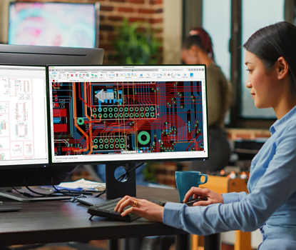 |
3, Trace Width and Spacing: Determine the appropriate trace width and spacing based on the desired impedance and current carrying capacity. Use impedance calculators or software tools to ensure accurate values. 4, Controlled Impedance: Maintain consistent track impedance throughout the PCB by carefully controlling the dielectric thickness, trace width, and spacing. This is crucial for high-frequency applications. 5, Via Design: Use via stitching techniques to connect the ground planes across different layers for better grounding and reduced ground impedance. 6, Component Placement: Carefully place high-frequency components to minimize trace lengths and optimize signal paths. Consider thermal management and EMI shielding requirements. 7, Power Integrity: Design an adequate power distribution network with appropriate decoupling capacitors and power plane structures to minimize voltage fluctuations and noise. |
8, Ground Plane: Include dedicated ground planes on adjacent layers to provide a low impedance return path for signal traces and minimize electromagnetic interference (EMI). 9, EMI/EMC Considerations: Implement EMI/EMC measures like proper shielding, filtering, and use of ground planes to reduce electromagnetic emissions and susceptibility. 10, Signal Routing: Follow best practices for signal routing, such as avoiding sharp corners, reducing vias, maintaining proper clearance, and minimizing crosstalk between adjacent traces. 11, Design Validation: Perform signal integrity simulations and analysis using specialized software tools to verify the performance of the design before fabrication. 12, Differential Pairs: For differential signals, ensure that the traces are routed as closely together as possible and maintain consistent spacing. Use differential pair routing guidelines for impedance matching. Remember, these are general guidelines, and the specific requirements for a Rogers Material PCB design may vary based on the intended application and the desired electrical characteristics. It is advisable to consult with an experienced PCB designer or manufacturer for more precise guidelines based on your specific project requirements. |
|
Why Choose PANDA PCB For Rogers PCB ? |
With years of experience in the PCB industry, PANDA PCB Group possesses extensive expertise in manufacturing high-quality Rogers PCBs. Our dedicated team of professionals is well-versed in the intricacies of Rogers materials and the specialized processes involved in producing top-notch Rogers PCBs. |
|
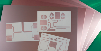 |
Panda PCB has increased the investment of production equipment and research and development on Rogers PCB field over the last few years, It is to meet to market development of the Rogers PCB for our customers from all around the world, We have rich experience in Rogers material PCB manufacturing of various Rogers PCB for the quick turn around prototypes and the mass production orders. Our standard Rogers PCBs could be made of under materials including : Kappa 438, RT/duroid® Laminates (RT/duroid 5870, RT/duroid 5880, RT/duroid 6006, RT/duroid 6010) , RO4000® Series (RO4350B, RO4003C , RO4700, RO4835) , RO3000® Series (RO3003, RO3010) , Also with other series, For example, AD350A, IsoClad 917, DiClad 870/880 etc. |
Raw Material Datasheet of Rogers PCB : |
Products |
Features |
Products |
Features |
Dk of 3.00 +/- 0.04 |
Dk of 3.50 (+/-0.05) |
||
Allows reverse treated foil to bond to standard RO4000® dielectric |
10x oxidation resistance compared to traditional thermoset laminates |
||
2.50 Dk +/-.04 |
3.50 Dk +/-.05 |
||
Dk of 2.17 or 2.20 |
Dk of 2.40 to 2.60 |
||
Dk of 2.17 or 2.20 |
Glass reinforced hydrocarbon thermoset platform |
||
Dk of 2.33 |
Dk of 2.20 |
||
Dk of 3.50 |
Dk of 6.15 |