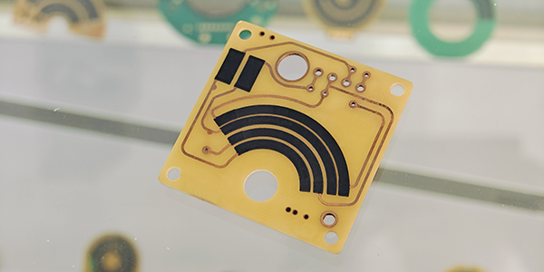
What is TPS PCB ?
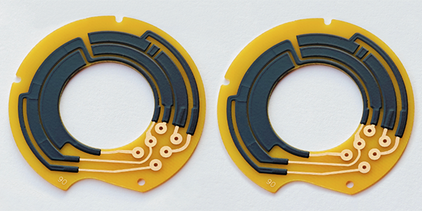
TPS PCBs, short for Throttle Position Sensor PCBs, are specialized circuit boards used in automotive throttle position sensors, utilizing thick film resistor technology on substrates such as ceramic, FR4, and flexible PI; their primary function is to accurately measure the extent to which the throttles are opened, a movement controlled by the driver through the accelerator pedals, with TPS PCBs converting the mechanical movements of the throttles into electrical signals that are processed by the Engine Control Units to adjust fuel injection and ignition timing, optimizing engine performance and fuel efficiency under various operating conditions.
TPS PCBs have several distinctive product features, the most notable being their high signal accuracy and stability. As the precise throttle positions directly impact engine control, TPS PCBs must ensure stable performance while withstanding factors like temperature fluctuations, vibrations, and humidity. To achieve these features, TPS PCBs incorporate high-performance sensors and optimize the layout and signal processing circuits of the boards.
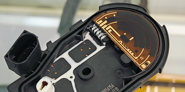
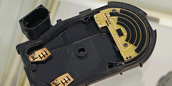
In terms of applications, TPS PCBs are widely used in modern automotive throttle control systems, playing a key role. As automotive technology continues to advance, especially with the widespread adoption of electronic control systems, the importance of TPS PCBs has grown. They not only improve engine response speed and fuel efficiency but also ensure smooth driving experiences and safety. Despite the harsh operating conditions of vehicles, TPS PCBs remain stable and reliable, making them indispensable components of automotive electronic systems.
Main Types and Working Principles of TPS PCB :
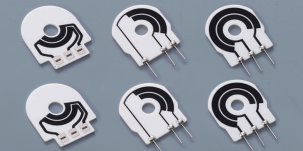
● Potentiometric Sensors (Throttle Potentiometer): These types of sensors use a variable resistor to measure the throttle's opening degree. As the throttle rotates, the resistance value of the resistor connected to the throttle shaft changes, thereby altering the voltage across the resistor. This changing voltage signal is then sent to the ECU (Engine Control Unit), which determines the throttle opening based on this signal. The advantages of potentiometric sensors are low cost and ease of implementation, but they also have issues with high wear and failure rates, and may exhibit nonlinear characteristics later in their life cycle.
● Hall Effect Sensors (Magnetic Systems): Hall effect sensors detect the throttle position based on changes in the magnetic field. These sensors typically include a Hall element and a permanent magnet. As the throttle shaft rotates, the position of the permanent magnet relative to the Hall element changes, causing a change in the voltage signal output by the Hall element. These types of sensors are contactless and therefore highly reliable, accurate, and have an excellent signal-to-noise ratio.
● Inductive Sensors (Inductive Systems): Inductive sensors use the principle of induction to measure the throttle's position. The sensor consists of a transmission coil and a receiving coil. The transmission coil sends a signal that is coupled back through a rotor into the receiving coil. These sensors are typically integrated onto a simple printed circuit board and use an integrated circuit to generate the excitation signal and decode the received signal.
● Optical Sensors and Other Technologies: Although optical systems or incremental encoders may lead in some aspects (such as resolution, linearity), their drawbacks in important areas (such as cost, reliability, high-temperature capability, etc.) are so prohibitive that these sensors are currently not widely used in throttle position sensor applications.
The types and working principles of Throttle Position Sensors PCB (TPS PCB) depend on the required accuracy, reliability, and cost-effectiveness. With technological advancements, more and more sensors are adopting contactless principles to improve reliability and reduce wear.
Key Characteristics of TPS PCB :
TPS PCBs (Throttle Position Sensor Printed Circuit Boards), which utilize thick film resistor technology and are commonly employed in automotive sensors, are distinguished by their production processes, features, and advantages as follows:
1, Production Process:
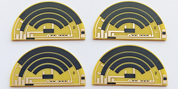
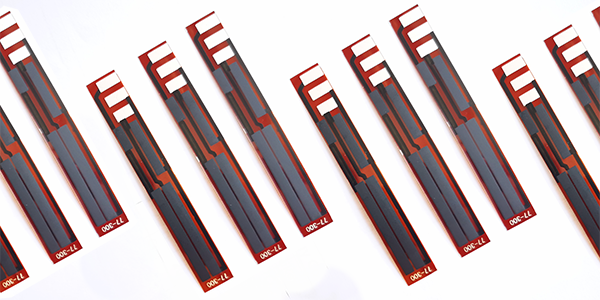
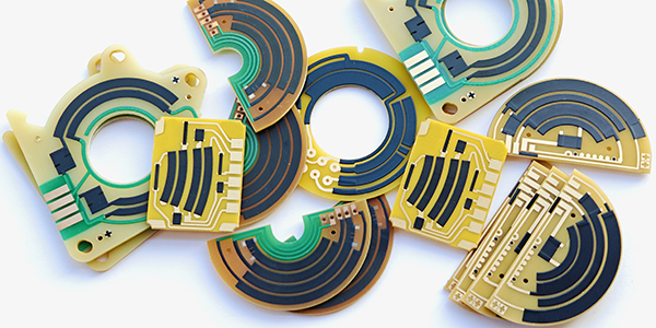
● The production of thick film sensors typically involves screen printing conductive paste onto a FR4, Flex PI, or Ceramic substrate, followed by drying and sintering. This process creates a resistive layer with a specific resistance value. For variable resistive sensors, the thick film resistive material is printed onto movable mechanical parts so that the resistance value changes as the mechanical part moves.
2, Features:
● Resistance Value Variation: The resistance value of thick film sensors changes with the mechanical part's displacement, which can be used to measure position, pressure, or other mechanical quantities.
● Temperature Coefficient: Thick film sensors often have a significant temperature coefficient, meaning their resistance values can change substantially with temperature variations. This may require additional temperature compensation measures to ensure sensor accuracy.
● Stability: Thick resistor sensors generally maintain stable performance over long periods and in various environmental conditions.
3, Advantages:
● Cost-Effectiveness: Compared to thin film sensors or other types of sensors, thick-film resistive sensors are less expensive to produce, making them more cost-effective for mass production.
● Simplicity of Process: The production process for thick film resistor sensors is relatively simple and easily automated, which helps to increase production efficiency and reduce costs.
● High-Temperature Resistance: Thick film resistive materials can typically withstand high operating temperatures, making them suitable for harsh environmental conditions.
● Corrosion Resistance: Thick film sensors have good corrosion resistance, making them suitable for use in chemically corrosive environments.
In the application of automotive throttle position sensors, TPS PCBs provide a voltage signal proportional to the throttle opening, which helps the Engine Control Unit to accurately control engine operation. Although they may require additional temperature compensation and long-term stability control, these sensors are widely used in the automotive industry due to their cost-effectiveness and reliability.
Why Thick Film Technology for TPS PCB ?
Thick film technology is ideal for TPS PCBs because it ensures precise printing of resistive materials, providing high-precision resistors for accurate throttle position detection. Its excellent thermal and mechanical properties allow the PCBs to withstand harsh automotive conditions, including temperature fluctuations and vibrations. Additionally, thick film technology is cost-effective for mass production, ensuring reliable quality while lowering manufacturing costs.
1, Basic Principle:
● A thick film resisor sensor typically contains a fixed resistive path, which is configured as a variable resistor (or potentiometer).
● When a mechanical component (such as a throttle shaft) moves, a sliding contact (or wiper) moves along the resistive path.
● As the position of the sliding contact changes, the resistance between it and the ends of the resistive path also changes.
2, Resistance Variation:
● The change in resistance alters the voltage drop across the resistance, as the voltage drop is proportional to the resistance.
● This voltage change can be detected by electronic circuits and converted into a corresponding signal to indicate the position of the mechanical component.
3, Precise Measurement:
● To achieve precise measurement, the sensor's design must ensure a linear change in the resistive path so that every position of the sliding contact produces a unique corresponding voltage output.
● The sensor must also have sufficient resolution, meaning that even minor changes in displacement should result in a detectable voltage change.
● The stability and repeatability of the sensor are also crucial to ensure consistency in long-term and multiple measurements.
4, Temperature Compensation:
● Since thick film resistor is sensitive to temperature changes, the sensor usually includes a temperature compensation mechanism to ensure accurate measurements across different temperatures.
5, Signal Processing:
● The voltage signal output by the sensor is typically weak and needs to be amplified, filtered, and converted by a signal conditioning circuit for easy reading and processing by electronic devices such as microcontrollers or ECUs.
6, Application Example:
● In automotive throttle position sensors, thick film resistor sensors can provide precise measurements of throttle opening, which is crucial for engine management systems as it affects the control of fuel injection and ignition timing.
TPS PCBs can achieve accurate and reliable measurements of mechanical displacement, finding widespread application in various industrial and automotive applications.
Specifications of TPS PCB :
Test Item |
Standard |
Test Method |
Linearity of Output Voltage |
Should be ≤ 1% |
Throttle Position Sensor PCB (TPS PCB) must maintain a linearity of output voltage that should not exceed ±1% to ensure precise throttle angle measurements. This linearity is tested by recording the sensor's output voltage in relation to the throttle's angular position over multiple full-range cycles. |
Wear Life (Durability) |
Over 5 million cycles |
Throttle Position Sensor PCB utilizes a platinum-palladium alloy wire sliding contact wiper, which ensures durability and reliability. The contact pressure with the resistive body is maintained at 0.15 N ± 0.05 N, and the sensor is designed to endure at least 5 million cycles of operation. |
Temperature Coefficient |
Within specified T.C.R |
Throttle Position Sensor PCB's resistive temperature coefficient is kept within specified limits as per IEC 60115-1 4.8, ensuring stable performance across a range of temperatures from +25°C to -40°C, and up to +125°C. |
Short Time Overload |
(△R/R)≤ 5% |
Throttle Position Sensor PCB is tested for short time overload conditions by applying a voltage of 16V for a period of 60 minutes, ensuring it can handle temporary voltage spikes. |
Rapid Temperature Changing |
(△R/R)≤ 5% |
Throttle Position Sensor PCB is subjected to rapid temperature changes, with cycles of -40°C for 30 minutes, a transition to normal temperature for 5 minutes, and then 125°C for 30 minutes, repeated for 5 cycles. |
Low Temperature Operation |
(△R/R)≤ 5% |
Throttle Position Sensor PCB's low-temperature operation is tested by placing it in a low-temperature chamber at -40°C, maintaining the temperature for 1 hour, and then applying a nominal voltage of (5 ± 0.1) V for 48 hours. |
Endurance at 70°C |
(△R/R)≤ 5% |
Throttle Position Sensor PCB's endurance is evaluated at a constant temperature of 70°C ± 2°C for 1000 hours, with a cycle of 1.5 hours ON and 0.5 hours OFF, using the rated voltage or the limiting element voltage, whichever is lower. |
Damp Heat Steady State |
(△R/R)≤ 5% |
Throttle Position Sensor PCB's performance in damp heat conditions is assessed at 40°C ±2°C and 93% ±3%RH for 1000 hours. |
Low Temperature Storage |
(△R/R)≤ 5% |
Thick Film Resistor is tested for storage at low temperatures of -40°C ±1°C for 1000 hours to ensure long-term stability. |
High Temperature Storage |
(△R/R)≤ 5% |
Thick Film Resistor is also tested for storage at high temperatures of 150°C ±1°C for 1000 hours to evaluate its resistance to prolonged exposure to heat. |
For more information, Please refer to Thick Film Sensors.