What is TFR PCB ?
TFR PCBs, short for Thick Film Resistor PCBs, are specialized printed circuit boards that incorporate resistors, sensors, heaters, or dividers onto their surface using thick-film resistor technology, which involves applying a thick-film conductive or resistive material, such as metal oxides, to substrates like FR4 or ceramics and then sintering the material at high temperatures to form resistors with specific resistance values, providing both electrical connectivity and resistance capabilities, making them essential components in various modern electronic devices.
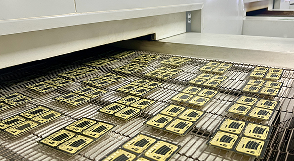
TFR PCBs are produced through a precise process that involves applying conductive or resistive thick-film materials onto substrates like FR4 or ceramics. These materials are sintered at high temperatures, allowing them to form resistors with specific resistance values. The manufacturing process requires meticulous control over material composition and sintering conditions to ensure the accuracy and reliability of the resistors. This careful process ensures that the TFR PCBs maintain high performance and durability, with integrated resistive components that optimize both space and efficiency.
TFR PCBs offer several key advantages, including a compact design that integrates resistors directly onto the PCB, reducing the need for traditional discrete resistors. This results in smaller, more efficient circuit boards. Additionally, TFR PCBs maintain stable resistance values across a broad temperature range, enhancing their reliability in various conditions. Their excellent durability and resistance to electrical interference make them ideal for applications where stability and longevity are vital.
TFR PCBs have a wide array of applications across many industries. In consumer electronics, they are commonly used in audio systems, televisions, and household appliances, providing precise resistance adjustment and signal processing. In automotive electronics, TFR PCBs are utilized in throttle and fuel level sensors, ensuring the proper functioning and safety of vehicles. As the demand for smart devices and the Internet of Things (IoT) grows, TFR PCBs are increasingly integrated into wearable devices and industrial control systems, becoming a vital component in modern electronics.
Material Comparisons of TFR PCB :
TFR PCBs can be produced based on different substrates, including Flex PI, FR4, and Ceramic. Each of these materials has unique advantages and disadvantages, which engineers must consider when designing TFR PCBs. Below is an analysis and comparison of these three substrates to help engineers make an informed choice during the design process.
1, Flex PI (Flexible Polyimide) :
Advantages:
● Flexibility: Flex PI is a highly flexible material, which makes it ideal for applications that require bending or folding. This is particularly useful for wearable devices, flexible circuits, and compact electronic designs.
● Lightweight: Being flexible and lightweight, it is perfect for portable applications where weight reduction is essential.
● Thermal Stability: Flex PI offers excellent thermal resistance, capable of withstanding high temperatures without degrading, making it suitable for environments with temperature fluctuations.
● Durability: It has good resistance to chemicals, radiation, and mechanical stresses, which enhances its longevity in harsh environments.
Disadvantages:
● Cost: Flex PI tends to be more expensive than FR4 and ceramic substrates due to the specialized manufacturing processes required.
● Lower Electrical Performance: While suitable for many applications, Flex PI may not offer the same level of electrical performance (e.g., insulation and signal integrity) as ceramic substrates.
● Complexity in Fabrication: The manufacturing process of flexible PCBs is more complicated and may involve additional steps compared to rigid PCBs, potentially increasing production time.
2, FR4 (Flame Retardant 4) :
Advantages:
● Cost-Effective: FR4 is widely used because it is relatively inexpensive compared to Flex PI and ceramic substrates. It is cost-effective for mass production.
● Good Mechanical Properties: FR4 has a good balance between mechanical strength and electrical performance, making it suitable for general-purpose applications.
● Ease of Fabrication: FR4 substrates are easy to fabricate, which simplifies the production process and reduces lead times.
● Widely Available: FR4 is a standard material used in most PCB designs, so it is readily available with well-established supply chains and manufacturing capabilities.
Disadvantages:
● Limited Thermal Performance: FR4 is not as thermally stable as ceramic substrates and can degrade under high-temperature conditions (typically above 130-140°C).
● Lower Resistance Stability: Compared to ceramic substrates, FR4 may not offer as high of a stable resistance over time, especially in harsh environments or extreme conditions.
● Mechanical Rigidity: FR4 is not flexible, so it may not be suitable for applications where bending or flexibility is required.
3,Ceramic (Alumina) :
Advantages:
● Superior Thermal Performance: Ceramic substrates offer excellent thermal conductivity and can withstand very high temperatures (up to 500°C or more), making them ideal for high-temperature applications.
● Excellent Electrical Performance: Ceramic materials have excellent insulation properties, leading to better signal integrity and lower electrical noise. This is important in sensitive electronics or applications requiring high-precision resistors.
● High Stability: Ceramic substrates provide highly stable resistance values and can maintain consistent performance in harsh environments, offering long-term reliability.
● High Durability: Ceramics are highly resistant to wear, corrosion, and mechanical stresses, providing superior durability in demanding conditions.
Disadvantages:
● Cost: Ceramic substrates are more expensive than both Flex PI and FR4, which can increase the overall cost of the PCB, especially for large-scale production.
● Brittleness: Ceramic materials are brittle and can crack under mechanical stress or improper handling, making them less suitable for applications where flexibility or impact resistance is critical.
● Complex Manufacturing Process: The production process for ceramic substrates is more complex and may require specialized equipment, leading to longer production times and potentially higher costs.
● Flex PI Material is the best choice for flexible and lightweight applications where the circuit must bend or move, such as in wearable electronics and flexible displays. However, it may not be suitable for extremely high-performance applications due to its higher cost and lower electrical performance.
● FR4 Material is ideal for general-purpose, cost-sensitive applications where mechanical strength and ease of fabrication are essential. It is best suited for most consumer electronics and general industrial applications but may not perform well under extreme thermal or electrical conditions.
● Ceramic Material is the optimal choice for high-performance, high-reliability applications where thermal stability, electrical precision, and durability are crucial. It is particularly suitable for high-temperature environments, sensitive electronics, and advanced industrial or automotive systems.
Each substrate has its specific use case, and the choice should be made based on the specific requirements of the TFR PCB design, including performance, cost, and environmental considerations.
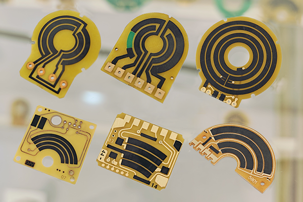
TFR PCBs in Automotive and Industrial Sensors :
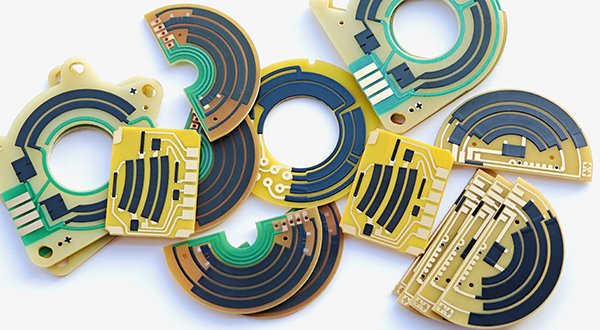
TFR PCBs (Thick Film Resistor PCBs ) are widely used in various sensors, especially in automotive electronics and industrial control sensors. The advantages of TFR PCBs lie in their high precision, high reliability, anti-interference capability, and the ability to withstand extreme operating environments. These features are especially important in automotive and industrial sensors, where temperature, humidity, and mechanical vibration are critical factors. Below is a detailed explanation of the role, design principles, and working principles of TFR PCBs in automotive and industrial control sensors.
1. Automotive Sensors :
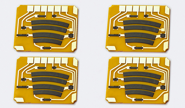
1.1 Fuel Level Sensor
● Role of TFR PCB:
In fuel level sensors, TFR PCBs typically serve as the resistance measurement unit, working with a float resistor or capacitive sensor to detect the fuel level in the tank. The TFR PCB provides high-precision resistive elements and is capable of stable performance in high-temperature and vibration environments, ensuring accurate fuel level signals.
● Design Principles:
When designing, TFR PCB's thick film resistive materials are selected for their excellent temperature stability to prevent resistance drift caused by temperature changes. The design also needs to be resistant to moisture and chemical corrosion, adapting to the automotive fuel environment.
● Working Principle:
As the fuel level changes, the float moves up and down, causing the resistance to change. The thick film resistive elements on the TFR PCB are connected to the float resistor, and the change in resistance is translated into an electrical signal that is transmitted to the vehicle's computer system, providing real-time monitoring of the fuel level.
● Role of TFR PCB:
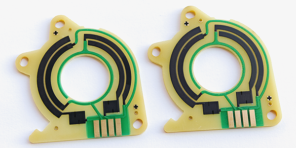
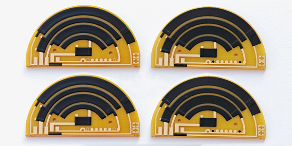
Throttle position sensors often use potentiometers (Variable Resistor) or Hall-effect sensors, with the TFR PCB providing a stable resistive layer and signal transmission path. It helps to accurately detect the throttle pedal's angle, ensuring that the Engine Control Unit (ECU) receives an accurate throttle input signal, which is then used to adjust fuel injection and engine output.
● Design Principles:
The design focuses on anti-interference and selecting high-precision resistive materials. The thick film resistor ensures stable operation within a wide temperature range, and the circuit layout must minimize mechanical vibration's impact on the sensor signal.
● Working Principle:
Changes in the throttle pedal's angle cause the resistance of the potentiometer inside the sensor to change. The TFR PCB’s resistive elements are part of a voltage divider network, where the movement of the pedal alters the voltage signal, which is then transmitted to the ECU to adjust the engine's power output.
● Role of TFR PCB:
Pedal position sensors are used to detect the position of the accelerator or brake pedals. TFR PCBs provide precise resistive elements and reliable signal transmission, ensuring that the sensor can accurately report the pedal's actual position.
● Design Principles:
When designing, TFR PCBs must consider the high temperatures and humidity in which the sensor typically operates. The thick film resistive materials provide excellent temperature stability, while the compact circuit layout effectively reduces electrical noise.
● Working Principle:
Pedal position sensors detect the movement of the pedal and cause a change in resistance or voltage. The TFR PCB’s resistive elements generate a reliable voltage signal based on these changes, which is then transmitted to the vehicle's electronic control system.
2. Industrial Control Sensors :
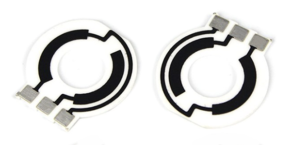
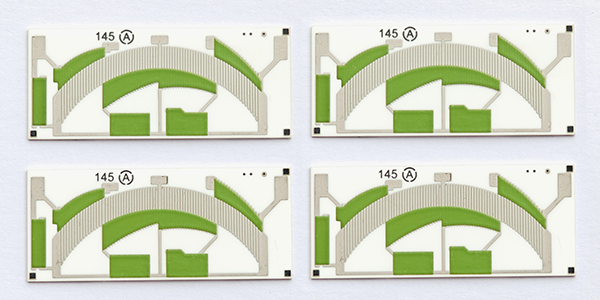
2.1 Potentiometer Sensor
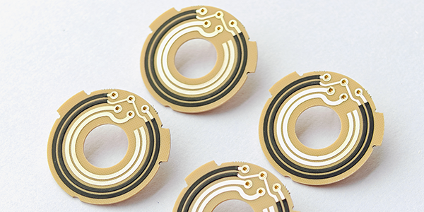
● Role of TFR PCB:
Potentiometer sensors are used to detect physical quantities such as position, angle, or displacement. TFR PCBs provide precise resistive layers, ensuring stable resistance and high accuracy during the sensor's operation. In industrial environments, TFR PCBs help minimize external interference, improving system reliability.
● Design Principles:
When designing, the thick film resistive materials on the TFR PCB must withstand long-term, high-load operation and maintain stable resistance even under significant temperature fluctuations. The circuit design typically includes anti-interference measures to improve the sensor's stability.
● Working Principle:
Potentiometer sensors use the principle of sliding resistance to measure changes in angle or position. As the potentiometer adjusts, the resistance value changes. The TFR PCB converts the resistance changes into corresponding voltage changes, which are transmitted to the control system for further processing.
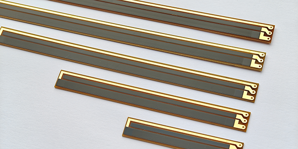
● Role of TFR PCB:
Position sensors are used to monitor the position of mechanical components and are commonly used in applications like robotics and automated equipment. TFR PCBs serve as the electrical platform for these sensors, providing stable resistive material support, with excellent heat resistance and anti-vibration capabilities, allowing them to function effectively in harsh industrial environments.
● Design Principles:
The thick film resistive technology of the TFR PCB effectively prevents temperature and environmental changes from affecting sensor accuracy. During the design, ensuring the stability of the sensor’s circuit and its resistance to electrical interference is crucial, especially in industrial settings where complex electromagnetic environments and mechanical vibrations are present.
● Working Principle:
Position sensors may work based on the Potentiometer (Variable Resistor), Hall effect, magnetic induction, or optical principles. They detect changes in resistor value, magnetic fields or light, which are then converted into electrical signals by the resistive elements on the TFR PCB. These signals are transmitted to the control system for accurate positioning.
TFR PCBs play a vital role in automotive and industrial control sensors by providing high-precision resistive components, excellent temperature stability, anti-interference, and mechanical shock resistance. These features ensure that sensors operate reliably in harsh environments. The design principles focus on maintaining stable resistance values and compact circuit layouts, while the working principles rely on changes in resistance, voltage, or current. TFR PCBs enable precise electrical signal transmission, allowing the sensors to perform a wide variety of detection tasks accurately and efficiently.
Process Capabilities of TFR PCB :
Items |
Typical Values |
1, Substrates : |
FR4, Alumina (Ceramic), Polyimide (Flexible PCB), Stainless Steel (SUS304), Mica |
2, Conductors Material : |
Copper, Silver , Gold , Silver-Palladium, Palladium-Gold |
3, Thick Film Carbon Thickness (height) : |
15um +/-5 um |
4, Silver Palladium Thickness (height) : |
12um+/-5um |
5, Minimum Width of Thick Film Traces : |
0.25 mm +/-0.05 mm |
6, Minimum Spacing of Thick Film Traces : |
0.25 mm +/-0.05 mm |
7, Minimum Footprint (Carbon to Copper) : |
No less than 0.20mm |
8, Sheet Resistivity (ohms/square): |
Printed resistors in milli ohm to mega ohm range (Customizable) with tolerances of 1-10% are fabricated and protected with overglaze materials |
9, Resistor Value Tolerance : |
+/-10.0% (Standard) (Customizable) |
10, Linearity : |
+/-1.0% (Standard) (Customizable) |
11, Synchronism of Potentiometers (Double Channels) : |
+/-2.0% (Standard) (Customizable) |
12, Durability of Carbon Ink (Life time) : |
0.5 Million (Min), 2.0-5.0 Million (Standard) |
13, Working Temperature : |
- 40℃ /+150℃ |
For more information, Please refer to Thick Film Resistor PCB.