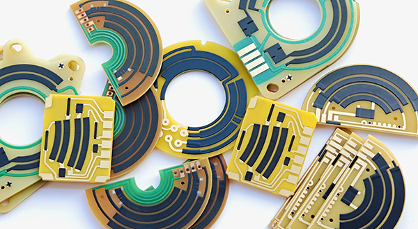
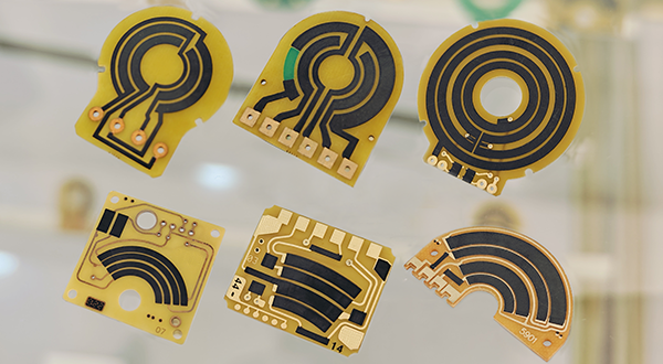
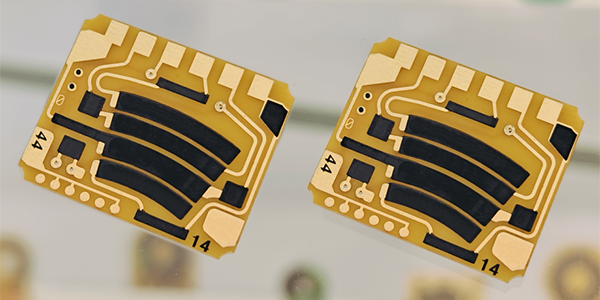
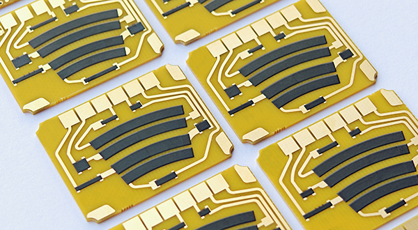
Pedal Position Sensor Carbon PCB
Pedal Position Sensor Carbon PCBs are crucial automotive electronic components that accurately detect the force and position of the accelerator pedal, converting these physical inputs into resistance changes, which are transmitted to the vehicle's Electronic Control Unit to regulate the engine's fuel supply, precisely controlling engine speed and output power, ultimately improving driving smoothness, optimizing fuel efficiency, and enhancing overall vehicle performance.
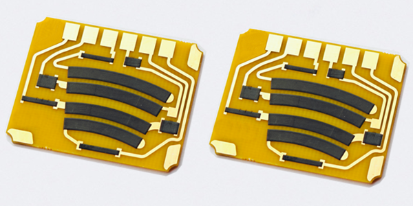
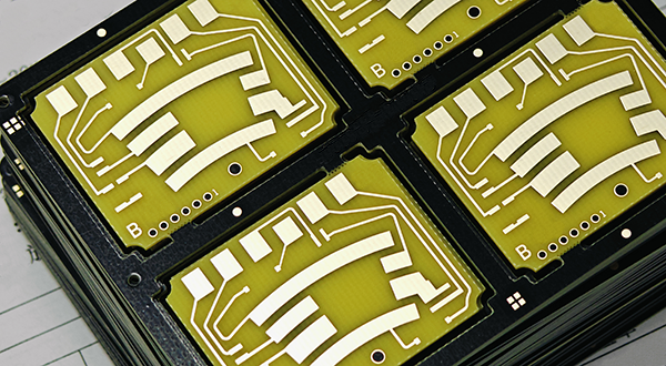
Pedal Position Sensor Carbon PCBs are manufactured using thick-film resistor technology, where conductive and resistive pastes are printed onto FR4 or ceramic substrates, then fused together through high-temperature sintering to ensure stability. Laser trimming is used to adjust the accuracy and linearity of the resistance, ensuring the sensor responds precisely to pedal movements. The surface may also undergo polishing to improve durability, and insulating resin is applied to protect the sensor from environmental factors.
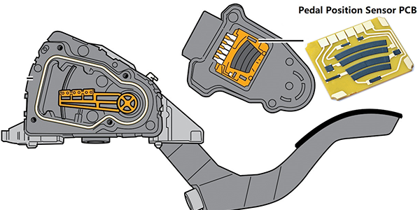
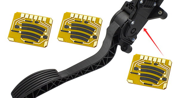
Pedal Position Sensor Carbon PCBs are widely used in modern automotive throttle control systems. They serve as crucial components enabling precise interaction between the engine and driver. By detecting changes in the accelerator pedal position and transmitting signals to the ECU, these sensors help regulate throttle and fuel injection to optimize engine performance, enhance driving smoothness, and improve fuel economy. With advances in automotive electronics, Pedal Position Sensor Carbon PCBs have become indispensable components in many types of passenger cars, commercial vehicles, and new energy vehicles.
Characteristics of Pedal Position Sensor Carbon PCB :
● Variable Resistance Technology:
The sensor board integrates a potentiometer-style variable resistor, which allows it to detect changes in the position of the accelerator pedal and translate these into variable electrical resistance.
● Conductive Carbon Paste:
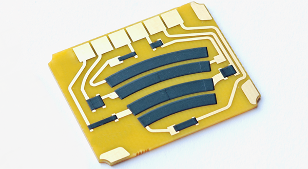
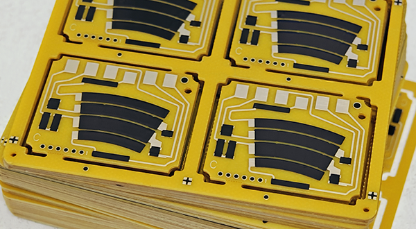
The use of conductive carbon paste ensures a reliable and consistent electrical conductivity path. This paste is printed onto the copper tracks of the PCB in a precise pattern to form the resistive element.
● High-Temperature Sintering:
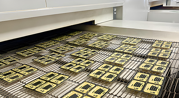
The carbon paste is subjected to high-temperature sintering, which solidifies the paste and creates a durable and stable resistive layer. This process enhances the sensor's long-term performance and reliability.
● Laser Trimming:
After the sintering process, laser trimming is employed to fine-tune the resistance values for accuracy and linearity. This ensures that the sensor provides precise and consistent readings across the full range of pedal positions.
● Polished Carbon Film:
The surface of the carbon film is polished to improve its durability and longevity. This step helps to maintain the sensor's performance over time and under various operating conditions.
● Insulating Resin Coating:
An insulating resin is applied to the sensor board to protect the conductive elements from environmental factors such as moisture, dust, and temperature fluctuations. This coating also helps to prevent physical damage and electrical shorts.
● High Sensitivity and Accuracy:
The sensor board is designed to be highly sensitive and accurate, providing precise measurements of pedal position changes. This is crucial for the vehicle's electronic control unit (ECU) to make accurate adjustments to engine performance.
● Long Service Life:
The combination of durable materials and robust manufacturing processes results in a long service life for the sensor board. It is built to withstand the rigors of daily use and harsh environmental conditions.
● Integration with Electronic Control Systems:
The sensor board is designed to seamlessly integrate with the vehicle's electronic control systems, providing essential data for the ECU to manage engine functions effectively.
● Compatibility and Versatility:
While primarily used in automotive applications, the technology and design principles behind the Pedal Position Sensor Carbon PCB can also be adapted for use in other industries where precise control and measurement of mechanical movement are required.
These technical features make the Pedal Position Sensor Carbon PCB a critical component in the modern automotive industry, contributing to improved vehicle performance, safety, and efficiency.
TPS PCB vs Pedal Position Sensor Carbon PCB :
● Pedal Position Sensor PCB (PPS PCB) is installed near the accelerator pedal to detect its travel and relay the driver’s acceleration intent to the Engine Control Unit (ECU). It typically has two output signals: one is the VPA signal, which outputs voltage in a linear relationship throughout the pedal's range, and the other is the VPA2 signal, which outputs a bias voltage deviating from the VPA signal. These signals help the ECU accurately assess the driver’s intent, controlling engine idle, acceleration, and deceleration. The structure and working principle of the pedal position sensor are similar to that of the throttle position sensor, often existing in variable resistor and Hall effect types.
● Throttle Position Sensor PCB (TPS PCB) is mounted on the throttle body and primarily functions to detect the throttle opening, converting this information into an electrical signal sent to the ECU. This serves as a basis for the ECU to determine engine operating conditions. The throttle position sensor can be of switch-type output or linear variable resistor output, translating throttle opening into a voltage signal for ECU adjustments of fuel injection and ignition timing.
Although they overlap in function, the pedal position sensor focuses more on detecting the driver’s intent, while the throttle position sensor measures the actual throttle opening. In modern vehicles, these sensors are often integrated to enhance system responsiveness and accuracy. Thus, while they can sometimes be viewed as a single component, technically, they monitor different physical quantities and may serve distinct roles in various systems, In summary as follows:
● Pedal Position Sensor PCB (PPS PCB) directly monitors the force applied by the driver through the accelerator pedal, sensing the acceleration intent. It converts foot actions into electrical signals sent to the ECU, which calculates the necessary torque and power output based on these signals, along with data from other sensors (such as vehicle speed and engine RPM), to control fuel injection and ignition timing.
● Throttle Position Sensor PCB (TPS PCB) monitors the actual throttle opening, which corresponds to the amount of air entering the engine. This sensor also converts the throttle opening into electrical signals sent to the ECU, which uses this information to precisely control the air-fuel mixture and engine intake, optimizing combustion efficiency and power output.
The collaborative functioning of both sensors ensures that the engine can adjust the air-fuel ratio and power output accurately based on driver demands and actual conditions, achieving smooth acceleration and efficient engine performance.
Linearity of Pedal Position Sensor Carbon PCB :
High precision in linearity is crucial for the Pedal Position Sensor Carbon PCB, as it directly affects vehicle control accuracy and driving safety. Here are several key points regarding the importance of high-precision linearity for the Pedal Position Sensor Carbon PCB :
● Precise Control: High-precision linear response ensures that the pedal position sensor accurately reflects the driver's input on the accelerator pedal, allowing the Engine Control Unit to precisely manage fuel supply and engine output, providing a smooth acceleration experience.
● Enhanced Safety: In emergencies, where quick responses are needed to avoid collisions, a high-precision sensor can quickly and accurately relay changes in pedal position, enabling the vehicle to react promptly and enhancing driving safety.
● Improved Fuel Efficiency: By precisely controlling fuel injection, a high-precision pedal position sensor helps enhance fuel efficiency, reduce unnecessary fuel consumption, and lower emissions, in line with increasingly stringent environmental standards.
● Enhanced Driving Experience: High-precision sensors provide more sensitive and direct throttle response, improving the driver’s experience, especially in situations requiring fine control of vehicle speed.
Adaptability to Different Driving Modes: Modern vehicles are often equipped with various driving modes, such as sport, comfort, or economy. A high-precision Pedal Position Sensor Carbon PCB can adapt to the throttle response characteristics of these different modes, providing a consistent driving experience for the driver.
Enhance Linearity for Pedal Position Sensor PCB :
In the production of the Pedal Position Sensor Carbon PCB, controlling the consistency of the carbon paste thickness after printing is crucial for ensuring the sensor's linearity and overall performance. The uniformity of the carbon film thickness directly affects the linear precision of the sensor, as consistent thickness ensures that changes in resistance correlate with changes in pedal position, providing accurate signals to the Engine Control Unit. To enhance the consistency of linearity, manufacturers can implement the following measures:
● Precise Screen Printing: Utilize high-precision screen printing techniques to control the thickness of the carbon paste, ensuring an even distribution of thickness across the PCB.
● Strict Sintering Process: Temperature control during the sintering process is critical for the final thickness and uniformity of the carbon film. By precisely managing sintering temperature and time, manufacturers can ensure that the organic carrier in the carbon paste fully evaporates, while solid particles melt to form a uniform conductive layer.
● Laser Trimming: After sintering and curing, use laser technology to finely adjust the resistance values to improve linearity. Laser trimming can precisely remove or add carbon film material to adjust the resistance values.
● Quality Control Testing: Implement a combination of online and offline testing throughout the production process to assess the linearity of each sensor, ensuring compliance with specifications.
● Use of High-Quality Carbon Paste Materials: Select high-quality carbon paste materials with better conductivity and stability to enhance the sensor's performance.
Specifications of Pedal Position Sensor Carbon PCB :
Typical Application: |
Automotive Pedal Position Sensor PCB |
Dual-Channel Potentiometers: |
P1=Tape Carbon Track (Variable Conductor) P2=Tape Carbon Track (Variable Conductor) |
Signal Output: |
Analog |
Electrical Range: |
10-60° (Customizable) |
Supply Voltage: |
5,0±6% VDC (Customizable) |
Linearity: |
<1,5% (Customizable by Laser Trimming) |
Synchronisation: |
<2.0% (Customizable) |
Current Per Channel: |
Max. 12mA (Customizable) |
Excess Voltage Resistance: |
18V (Customizable) |
Output Signal 1: |
8 to 85±2% Supply Voltage (0° to 20°) (Customizable) |
Output Signal 2: |
3 to 60±2% Supply Voltage (0° to 20°) (Customizable) |
Temperature Range: |
-40°C to +125°C |
Material: |
FR4, TG170 (Fiberglass), 1.0mm+/-10% (Customizable) |
Copper Thickness: |
1oz (35um) (Customizable) |
Surface Finish: |
Immersion Gold (ENIG) + Thick Film Resistor |
Wear-Resistant Life (Durability): |
Standard 5,000,000 times (Customizable) |
Resistance and Tolerance: |
Customizable, Tolerance+/-10% or +/-15% |
For more information, Please refer to Thick Film Sensors.
Custom Thick Film Sensors
- Custom Thick Film Sensor Elements
- Fuel Level Sensor PCB
- Fuel Level Sensor Ceramic PCB
- Oil Level Sensor Ceramic PCB
- Motorcycle Fuel Level Sensor PCB
- Throttle Position Sensor PCB
- Throttle Position Sensor FR4 PCB
- Throttle Position Sensor Ceramic PCB
- Throttle Position Sensor Flexible PCB
- Accelerator Pedal Sensor PCB
- Accelerator Pedal Position Sensor PCB
- Pedal Position Sensor Carbon PCB
- Potentiometer PCB
- Linear Potentiometer Carbon Track PCB
- Rotary Potentiometer Carbon Track PCB
- FR4 Potentiometer Carbon PCB
- Ceramic Potentiometer Carbon PCB
- Flexible Potentiometer Carbon PCB
- Logarithmic Taper Potentiometer PCB
- Position Sensor PCB
- FR4 Position Sensor Carbon PCB
- Ceramic Position Sensor Carbon PCB
- Flexible Position Sensor Carbon PCB
- Flexible Sensor PCB
- Printed Flexible Electronic PCB
- Printed Carbon PCB
- Ceramic Pressure Sensors
- Ceramic Thick Film Pressure Sensors
- Engine Oil Pressure Sensor PCB
- Gold Coated Ceramic Substrates
- Gold Coated Thick Film Substrates
- Metallized Ceramic Substrates
- Multilayer Thick Film Substrates
- Thick Film Metallization Technology
- Thin Film Metallization Technology
- Thin Film Ceramic PCB
- Variable Resistor Carbon PCB
- Remote Ready Sender Ceramic PCB
- LP Gas Tank Gauges Ceramic PCB
- Thick Film Capacitive Sensors
- Thick Film Capacitive Pressure Sensors
- Thick Film Edible Oil Quality Sensors
- Thick Film Meteorological Rainfall Sensors
- PI Interdigital Electrodes (Flexible)
- Air Door Actuator PCB
- HVAC Blend Door Actuator PCB