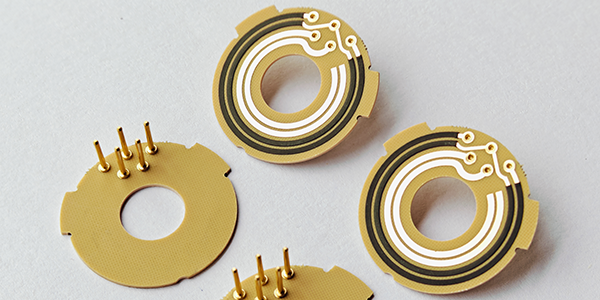
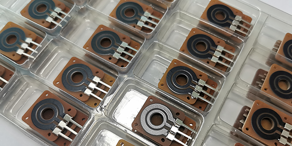
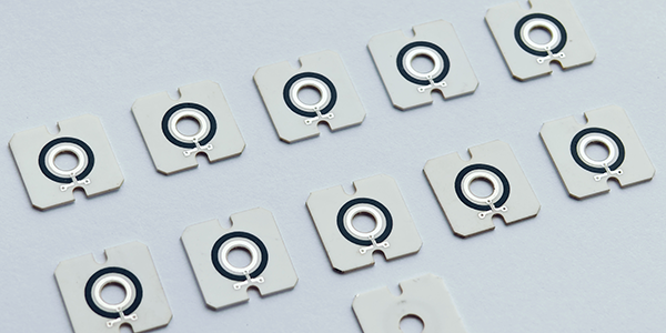
Potentiometer PCB
Potentiometer PCBs, also called Potentiometer Carbon PCBs, are electronic components that integrate variable resistor sensors into PCBs, using movable wiper contacts to slide along resistance tracks and alter resistance values, thereby adjusting current or voltage in circuits, which allows precise control over electrical characteristics and makes them versatile for applications such as volume controls, brightness adjustments, and power regulation, while modulating current and voltage in a customizable and controllable manner, playing crucial roles in various electronic systems.
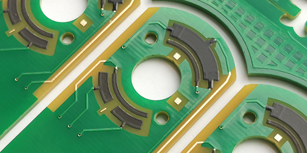
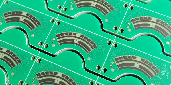
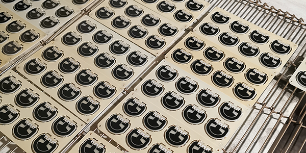
Potentiometer PCBs are produced through precise steps to ensure accuracy and long-term reliability. Conductive carbon paste is printed onto the surface using thick film resistor technology in pre-designed track patterns, followed by high-temperature sintering to solidify the resistive materials for stable performance. Laser trimming is then used to fine-tune the resistance values and improve response linearity. Finally, the carbon film surfaces are polished to enhance durability and ensure efficient performance in their intended applications.
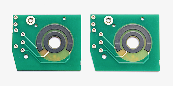
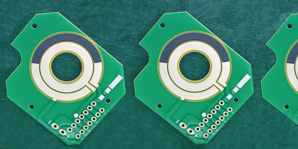
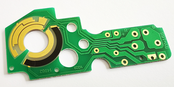
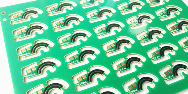
Potentiometer Carbon PCBs are known for their flexibility, precision, and durability. Potentiometer PCBs can be customized in terms of resistance values, track shapes, sizes, and mounting methods to suit a wide range of applications. Potentiometer PCBs are particularly valued for their high accuracy in adjusting electrical parameters and their cost-effectiveness in mass production. Potentiometer PCBs utilize a carbon-based resistance track that provides excellent wear resistance and longevity, ensuring reliable performance over time. Furthermore, Potentiometer PCBs are compact, making them ideal for use in both consumer electronics and industrial control systems that require efficient use of space.
Potentiometer Carbon PCBs are used in a wide range of applications where precise control over electrical parameters is necessary. In consumer electronics, Potentiometer PCBs are commonly employed in volume controls for audio equipment, brightness adjustments in displays, and power regulation in various devices. In industrial applications, Potentiometer PCBs are used for position sensing in machinery, as well as in temperature control systems and power supply regulation. Potentiometer PCBs' versatility makes them ideal for use in medical devices, automotive systems, and robotics, where they help adjust mechanical or electrical systems. Their adaptability and reliability make Potentiometer PCBs essential in both high-precision and cost-sensitive applications across various industries.
Manufacturing Processes of Potentiometer PCB :
● Thick Film Resistor Technology: Potentiometer PCBs are produced using thick film resistor technology, which allows for the creation of thicker resistance layers on the PCB, providing stable resistance values and good durability.
● Conductive Carbon Paste: Conductive carbon paste is used as the resistance material, forming stable conductive tracks during the high-temperature sintering process.
● High-Temperature Sintering: After printing the carbon paste, a high-temperature sintering process is required, which helps improve the stability and adhesion of the resistance layer.
● Laser Trimming: The resistance value is precisely adjusted through laser trimming, ensuring the accuracy and linearity of the potentiometer.
● Polished Carbon Film Surface: The surface of the sintered carbon film is polished to enhance its durability and reduce friction, thereby improving the lifespan of the potentiometer.
● Insulating Protective Layer: To protect other conductive traces and provide good insulation properties, a layer of insulating resin can be printed over the copper or silver tracks.
● Integrated Potentiometer Sensor: These Potentiometer PCBs integrate a potentiometer sensor with variable resistance functionality on their surface, suitable for various applications requiring resistance adjustment.
● Durability and Reliability: Due to the high-temperature sintering and polishing processes, Potentiometer PCBs typically exhibit high durability and reliability.
Working Principle of Potentiometer PCB :
Potentiometer PCBs operate on the principle of a movable wiper contact sliding along a resistive track to adjust resistance, controlling voltage or current in a circuit. This enables precise control over characteristics like brightness, volume, or power, making Potentiometer PCBs versatile for applications in audio equipment, lighting, and industrial machinery. With linear or logarithmic resistance options, they provide smooth volume control or align with the human ear's perception of loudness.
● Resistive Element: Potentiometer PCB includes a resistive element, which is typically a carbon film track made by printing and sintering conductive carbon paste.
● Sliding Contact (Wiper): Associated with the resistive element is a sliding contact or wiper, which can move along the resistive track.
● Voltage Division: When both ends of the potentiometer (usually the two fixed terminals) are connected to a voltage, the position of the wiper determines the voltage division between the wiper and either fixed terminal.
● Adjustment: By moving the wiper, the point of contact with the resistive track can be changed, thereby altering the resistance value between the wiper and the fixed terminal, and consequently changing the voltage or current in the circuit.
● Output Voltage: Potentiometer PCBs can be used as a voltage divider. As the wiper moves along the resistive track, an output voltage related to the wiper's position can be obtained at the wiper contact point.
● Applications: Potentiometer PCBs can be used for volume control, brightness adjustment, power supply voltage regulation, temperature control circuits, and a variety of applications.
Potentiometer PCBs operate on a working principle that makes them highly flexible electronic components, capable of achieving precise resistance adjustments in various electronic devices and circuits.
Advantages of Potentiometer Carbon PCB :
● Cost-Effectiveness: By directly printing conductive carbon elements on the PCB instead of traditional potentiometers, it effectively saves assembly space for the product, and significantly reduces manufacturing costs by eliminating the need for separate potentiometer components.
● Design Flexibility: Potentiometer Carbon PCBs allow designers to directly design resistance tracks on the PCB, thereby achieving the required resistance values, track shapes, and sizes to meet different application needs.
● Durability: Potentiometer Carbon PCBs typically have a long service life because they can withstand a large number of mechanical operation cycles, which is very important for applications that require frequent adjustments.
● Integration: Integrating the potentiometer function directly into the PCB simplifies the product assembly process, reduces the number of components, and helps to improve product reliability.
● Miniaturization: Potentiometer Carbon PCBs can be designed to be very thin and small, suitable for applications with limited space.
● Performance: Potentiometer Carbon Track PCBs can provide stable resistance performance, including carbon resistance values, sheet resistance values, and linear tolerances, which are crucial for ensuring circuit performance.
● Wide Application: Potentiometer Carbon PCBs are suitable for various fields, including industrial control, automotive, medical equipment, household appliances, and audio equipment.
● Easy Maintenance: Due to the durability and reliability of carbon track PCBs, they usually require less maintenance, which helps to reduce the total cost of product ownership.
● Environmental Adaptability: Potentiometer Carbon PCBs can work stably under various environmental conditions, including environments with significant temperature and humidity changes.
● Technological Maturity: The technology of Potentiometers is very mature, which makes them highly predictable in terms of performance and reliability.
Potentiometer Carbon PCBs provide a cost-effective, flexible, durable, and versatile solution by integrating the potentiometer function into the PCB.
Applications of Potentiometer PCB :
Potentiometer PCBs are used across multiple industries, with the following specific application examples:
● Automotive Industry: Used in headlight position sensors, ride height measurement, steering angle measurement, suspension control, and throttle control.
● Home Appliances: In home appliances, Potentiometer PCBs can be used for volume adjustment, temperature control, and function selection.
● Industrial Control: In the industrial control sector, Potentiometer PCB can be utilized for actuator position sensing, valve positioning, motor control modules, and blower motors.
● Medical Devices: In medical equipment, Potentiometer PCBs can adjust and control the functions of devices.
● Audio Equipments: Used in audio control, musical devices, and sound systems for adjusting volume and tone.
● Industrial Automation: In industrial automation machinery, Potentiometer PCB can control the movement and position of machines.
● Telecommunication Equipments: In telecommunication devices, Potentiometer PCB are used for antenna amplifiers, receivers, video communication, and internal communication.
● Measurement and Testing Equipmens: Used for precise measurement and adjustment of resistance values in devices.
● Plastic Injection Molding Machines: In plastic injection molding machines, Potentiometer PCB can control parameters during the injection process.
● Agricultural Machinery: In agricultural machinery, they can control and adjust the steering systems of heavy equipment.
These applications demonstrate the versatility and adaptability of Potentiometer PCBs, making them indispensable components in various electronic devices and systems.
Types of Potentiometer Carbon PCB :
Linear Potentiometer Carbon PCB and Rotary Potentiometer Carbon PCB are two common types of Potentiometer Carbon Track PCBs, primarily distinguished by their adjustment methods and application scenarios. Linear potentiometers are typically used in situations that require precise and predictable adjustments, while rotary potentiometers are better suited for applications that need continuous and smooth adjustments.
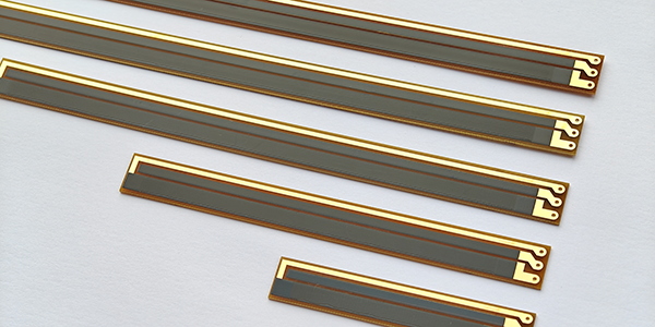
1, Linear Potentiometer Carbon PCB:
● Resistance Variation Pattern: The resistance of a linear potentiometer changes linearly with the angle of movement or rotation. This means that as the wiper or knob of the potentiometer moves, the resistance value changes uniformly, resulting in an output voltage that is proportional to the rotation angle or sliding distance.
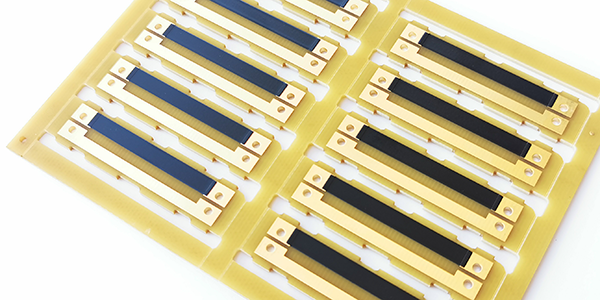
● Adjustment Method: Linear potentiometers can be single-turn or multi-turn. A single-turn potentiometer returns to its starting position after one or several turns, while a multi-turn potentiometer can rotate continuously for multiple turns, allowing for finer adjustments.
● Functionality: The resistance value of a linear potentiometer changes linearly with the position of its wiper, providing a voltage or resistance change that is proportional to the wiper’s position. This characteristic makes linear potentiometers ideal for applications requiring precise control of voltage or current.
● Applications: They are commonly used in electronic devices for volume control, analog signal adjustments, instrument calibration, and any situation that requires linear adjustments. For example, in audio systems, linear potentiometers can control signal gain or adjust measurement parameters in precision measurement devices.
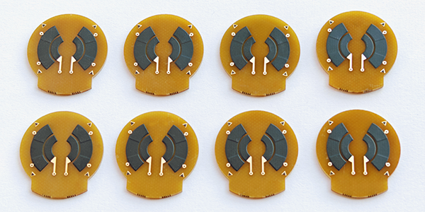
2, Rotary Potentiometer Carbon PCB:
● Resistance Variation Pattern: The resistance variation of a rotary potentiometer can be linear, logarithmic, or exponential, depending on its design. For instance, a logarithmic potentiometer (Type C) exhibits smaller resistance changes at the beginning of rotation, with larger changes occurring as the angle approaches the maximum resistance end.
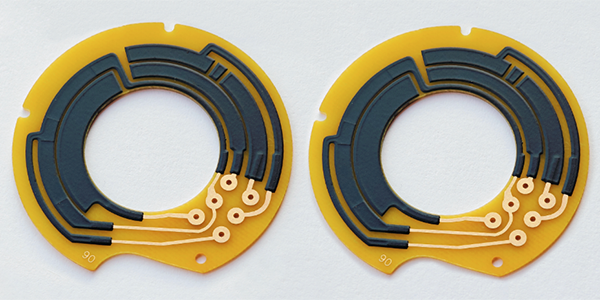
● Adjustment Method: Rotary potentiometers use rotational motion to change their resistance values, typically for obtaining adjustable supply voltages for certain electronic circuits.
● Functionality: Rotary potentiometers change their resistance values through rotation, commonly used in applications that require continuous adjustment. They can be either linear or logarithmic (where the change in resistance is exponentially related to the rotation angle), depending on their design and purpose.
● Applications: Rotary potentiometers are widely used in communication devices, car audio systems, household appliances, medical equipment, and other scenarios requiring continuous adjustments. For example, in car audio systems, rotary potentiometers can adjust volume or balance. They are also frequently used in industrial control and instrument adjustments, where non-linear adjustments may be needed, such as temperature or pressure control.
Material Selections of Potentiometer PCB :
When manufacturing Potentiometer PCBs, the common substrate materials include FR4, Ceramic, and Flexible PI. Here's a comparative introduction to the advantages and disadvantages of these three substrate materials:
1, FR4 Potentiometer Carbon PCB :
Advantages:
● Cost-Effectiveness: FR4 is the most common PCB substrate material, and due to its widespread use, it is relatively low in cost.
● Good Electrical Properties: FR4 has good insulation and mechanical strength, making it suitable for most electronic applications.
● Easy to Process: FR4 is easy to manufacture and fabricate, compatible with various PCB production techniques.
Disadvantages:
● Limited Heat Resistance: Although FR4 can operate at higher temperatures, it has lower heat resistance compared to ceramic substrates.
● Relatively High CTE: This can affect the stability of the circuit under temperature changes.
2, Ceramic Potentiometer Carbon PCB :
Advantages:
● High Thermal Conductivity: Ceramic substrates have excellent thermal conductivity, which is helpful for heat dissipation and suitable for high-power applications.
● Good Electrical Insulation: Ceramic materials have high electrical insulation properties, making them ideal for high-frequency circuits.
● Thermal Stability: Ceramics have a low coefficient of thermal expansion, making them suitable for operation under extreme temperatures.
Disadvantages:
● Higher Cost: Compared to FR4, ceramic substrates are more expensive.
● Processing Difficulty: Due to the high hardness of ceramic materials, they are more difficult and costly to process.
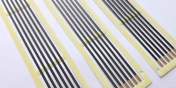
3, Flexible PI Potentiometer Carbon PCB :
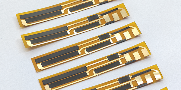
Advantages:
● Flexibility: PI substrates have good flexibility, making them suitable for applications that require bending or curling.
● High-Temperature Resistance: PI substrates can operate stably in high-temperature environments.
● Chemical Resistance: PI substrates have good resistance to a variety of chemicals.
Disadvantages:
● Higher Cost: The cost of PI substrates is usually higher than that of FR4.
● Electrical Properties: Although PI substrates have excellent mechanical properties, their electrical properties may not be as good as those of ceramic substrates.
When selecting a substrate material for Potentiometer PCBs, it is necessary to balance the specific requirements of the application and the budget. For instance, if the application requires high power handling and excellent heat dissipation, ceramic might be a better choice. If considering a balance between cost and electrical performance, FR4 might be a more suitable choice. For applications requiring flexibility, PI substrates are the ideal choice.
Process Capabilities of Potentiometer PCB :
Items |
Typical Values |
1, Substrates : |
FR4, Alumina (Ceramic), Polyimide (Flexible PCB), Stainless Steel (SUS304), Mica |
2, Conductors Material : |
Copper, Silver , Gold , Silver-Palladium, Palladium-Gold |
3, Thick Film Carbon Thickness (height) : |
15um +/-5 um |
4, Silver Palladium Thickness (height) : |
12um+/-5um |
5, Minimum Width of Thick Film Traces : |
0.25 mm +/-0.05 mm |
6, Minimum Spacing of Thick Film Traces : |
0.25 mm +/-0.05 mm |
7, Minimum Footprint (Carbon to Copper) : |
No less than 0.20mm |
8, Sheet Resistivity (ohms/square): |
Printed resistors in milli ohm to mega ohm range (Customizable) with tolerances of 1-10% are fabricated and protected with overglaze materials |
9, Resistor Value Tolerance : |
+/-10.0% (Standard) (Customizable) |
10, Linearity : |
+/-1.0% (Standard) (Customizable) |
11, Synchronism of Potentiometers (Double Channels) : |
+/-2.0% (Standard) (Customizable) |
12, Durability of Carbon Ink (Life time) : |
0.5 Million (Min), 2.0-5.0 Million (Standard) |
13, Working Temperature : |
- 40℃ /+150℃ |
For more information, Please refer to Thick Film Potentiometer PCB.
Custom Thick Film Sensors
- Custom Thick Film Sensor Elements
- Fuel Level Sensor PCB
- Fuel Level Sensor Ceramic PCB
- Oil Level Sensor Ceramic PCB
- Motorcycle Fuel Level Sensor PCB
- Throttle Position Sensor PCB
- Throttle Position Sensor FR4 PCB
- Throttle Position Sensor Ceramic PCB
- Throttle Position Sensor Flexible PCB
- Accelerator Pedal Sensor PCB
- Accelerator Pedal Position Sensor PCB
- Pedal Position Sensor Carbon PCB
- Potentiometer PCB
- Linear Potentiometer Carbon Track PCB
- Rotary Potentiometer Carbon Track PCB
- FR4 Potentiometer Carbon PCB
- Ceramic Potentiometer Carbon PCB
- Flexible Potentiometer Carbon PCB
- Logarithmic Taper Potentiometer PCB
- Position Sensor PCB
- FR4 Position Sensor Carbon PCB
- Ceramic Position Sensor Carbon PCB
- Flexible Position Sensor Carbon PCB
- Flexible Sensor PCB
- Printed Flexible Electronic PCB
- Printed Carbon PCB
- Ceramic Pressure Sensors
- Ceramic Thick Film Pressure Sensors
- Engine Oil Pressure Sensor PCB
- Gold Coated Ceramic Substrates
- Gold Coated Thick Film Substrates
- Metallized Ceramic Substrates
- Multilayer Thick Film Substrates
- Thick Film Metallization Technology
- Thin Film Metallization Technology
- Thin Film Ceramic PCB
- Variable Resistor Carbon PCB
- Remote Ready Sender Ceramic PCB
- LP Gas Tank Gauges Ceramic PCB
- Thick Film Capacitive Sensors
- Thick Film Capacitive Pressure Sensors
- Thick Film Edible Oil Quality Sensors
- Thick Film Meteorological Rainfall Sensors
- PI Interdigital Electrodes (Flexible)
- Air Door Actuator PCB
- HVAC Blend Door Actuator PCB