Throttle Position Sensor PCB
Throttle Position Sensor PCBs are essential components in modern automotive electronic systems, playing a critical role in the precise monitoring and regulation of throttle valve positions; designed to detect and report the position of the throttle valve, these PCBs directly influence the air-fuel mixture in the engine and provide vital information to the Engine Control Unit, which uses it to adjust fuel injection and ignition timing, optimizing engine performance, fuel efficiency, and emissions control, while helping to maintain engine stability, reduce fuel consumption, and minimize harmful emissions.
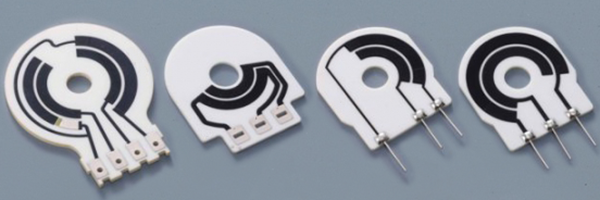
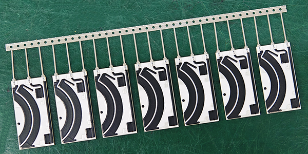
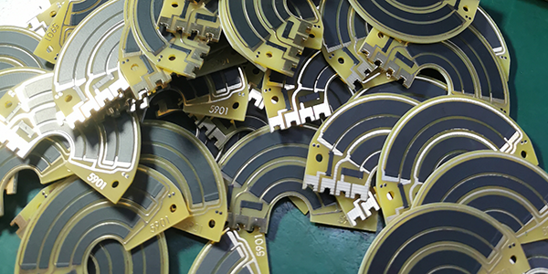
Throttle Position Sensor PCBs are produced using advanced manufacturing technologies to ensure high precision and reliability. The production process utilizes thick film hybrid circuit technology, which integrates resistors directly into the PCB structure, eliminating the need for additional components. Common materials, including ceramics, FR4, and flexible PI substrates, enhance durability and performance. This method also removes the need for expensive termination treatments like silver-palladium or gold-palladium, making the production process more cost-effective. Laser trimming is employed to fine-tune resistor values, ensuring the PCBs meet strict specifications. The use of stable binder systems further improves overall reliability and longevity.
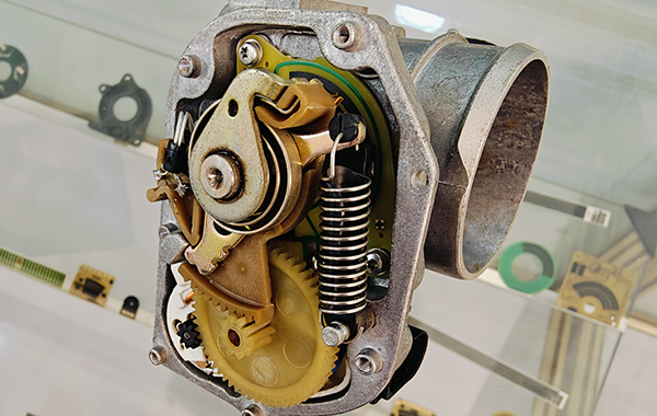
Throttle Position Sensor PCBs are characterized by their precision, durability, and efficiency. Designed to withstand harsh automotive environments, including high temperatures, vibrations, and exposure to moisture, these PCBs ensure that the signals transmitted to the Engine Control Unit are accurate and responsive. The integration of electronic circuitry with mechanical components such as potentiometers or Hall-effect sensors ensures reliable performance. Additionally, these PCBs support faster and more accurate vehicle diagnostics, contributing to the overall functionality of modern vehicles and making them an indispensable part of automotive electronics.
Features of Throttle Position Sensor PCB :
Throttle Position Sensor PCBs, developed utilizing thick-film resistive technology, are recognized for its distinctive features that are highly beneficial in automotive applications.
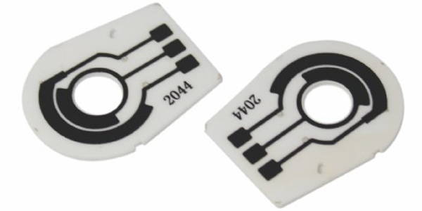
● High-Precision Resistive Technology: Throttle Position Sensor PCBs are crafted with thick-film resistive technology that ensures the precision of the throttle position sensor, translating the throttle's position into an accurate electrical signal.
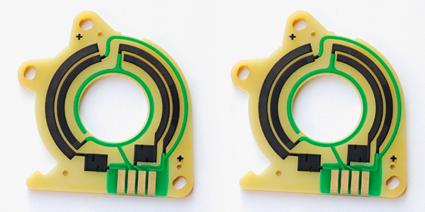
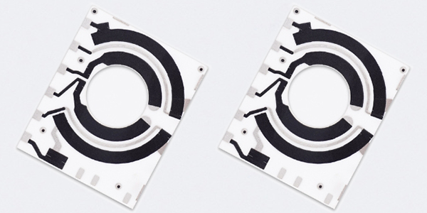
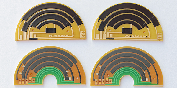
● Advanced Substrate Options: Substrate materials for these PCBs can be chosen from ceramic, FR4, or Polyimide (PI), each offering unique properties such as thermal stability and mechanical strength.
● Precious Metal Conductors: The use of silver palladium or gold palladium inks printed on the substrate and then sintered at high temperatures ensures the creation of a conductive path that is resistant to corrosion and offers excellent electrical conductivity.
● High-Temperature Sintering Process: Thick-film inks are cured through a high-temperature sintering process, which solidifies the conductive pattern on the PCB and enhances its durability.
● Precision Laser Trimming: After the thick-film printing process, laser trimming is employed to fine-tune the resistance values and linearity, ensuring the Throttle Position Sensor PCB meets stringent accuracy requirements.
● Long Service Life: The robust materials and meticulous manufacturing processes result in a Throttle Position Sensor PCB with an extended service life, capable of withstanding the demands of automotive environments.
● Reliability and Stability: Throttle Position Sensor PCB is designed for high reliability and stability, which is critical for consistent performance in automotive throttle control systems.
● Environmental and Mechanical Resistance: The choice of materials and the sintering process confer resistance to various environmental factors, including temperature extremes, humidity, and chemicals, as well as mechanical stress.
● Customizable Resistance Characteristics: Throttle Position Sensor PCB can be tailored to have specific resistance values and linearity curves, optimizing its performance for different automotive applications.
● Automotive-grade Quality: The manufacturing process adheres to stringent automotive-grade quality standards, ensuring the Throttle Position Sensor PCB's suitability for use in critical vehicle control systems.
These features make the throttle position sensor PCBs an integral component in modern automotive throttle control systems, providing a reliable and accurate method for translating the driver's throttle input into electrical signals that the vehicle's engine control unit can process effectively.
Substrates Choice of Throttle Position Sensor PCB :
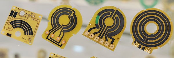
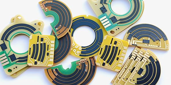
Throttle Position Sensor PCBs rely on the choice between Ceramic, FR4, and Polyimide (PI) substrates, with the selection depending on factors such as thermal performance, mechanical strength, electrical properties, and cost considerations.
1, Ceramic Substrates: Known for their high thermal conductivity, which makes them ideal for high-power applications where efficient heat dissipation is necessary. Ceramic substrates also exhibit excellent electrical insulation properties and high-temperature resistance, making them suitable for high-frequency applications. However, they tend to be more brittle and can be more challenging and expensive to manufacture compared to FR4. Please refer to Throttle Position Sensor Ceramic PCB for more informations.
2, FR4 Substrates: As the most common PCB material, FR4 offers a good balance between cost, mechanical strength, and electrical performance. It has a lower thermal conductivity compared to ceramic but is known for its ease of manufacturing and versatility. FR4 is widely used in various electronic devices due to its good electrical properties, including a low dielectric constant and dielectric loss, making it suitable for high-frequency applications. Despite its lower thermal conductivity, FR4 can still handle moderate heat dissipation requirements, and its limitations can be mitigated with effective heat dissipation designs. Please refer to Throttle Position Sensor FR4 PCB for more informations.
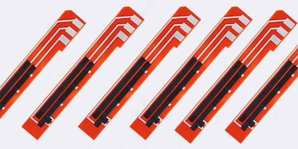
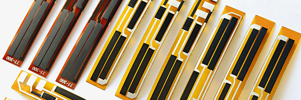
3, Flexible Polyimide (PI) Substrates: PI is a flexible material that is well-suited for flexible circuit boards (FPC) and rigid-flex boards due to its flexibility and bendability. It has high-temperature resistance and excellent electrical properties, making it suitable for high-frequency applications. PI substrates are appreciated for their lightweight, which is beneficial for miniaturization and lightweight design. However, the specific properties of PI in relation to Throttle Position Sensor PCBs are not detailed in the provided resources. Please refer to Throttle Position Sensor Flexible PCB for more informations.
The selection of the substrate material for Throttle Position Sensor PCBs should be based on the specific requirements of the application, including thermal management, mechanical robustness, electrical performance, and cost-efficiency. Ceramic offers superior thermal and electrical properties at a higher cost, FR4 provides a balanced and cost-effective solution, and PI brings flexibility and high-temperature resistance for specialized applications.
Processes of Throttle Position Sensor PCB :
Throttle Position Sensor PCBs rely on a manufacturing process that involves multiple precision steps to ensure the sensor's high accuracy and reliability. Here are the key steps in the manufacturing process of the Throttle Position Sensor PCB:
● Substrate Selection: Start by selecting the appropriate substrate material, such as ceramic, FR4, or Polyimide (PI). These substrates determine the PCB's thermal performance, mechanical strength, and electrical characteristics.
● Circuit Design: Design the sensor's circuit diagram, including the layout of thick-film resistors and other necessary electronic components. The circuit design must ensure that the sensor can accurately convert the throttle valve's position changes into electrical signals.
● Conductor Material Printing: Print silver palladium or gold palladium paste on the substrate. These materials form conductors after high-temperature sintering. This step is crucial for ensuring the sensor's electrical conductivity and durability.
● Thick-Film Resistor Printing: Print thick-film resistors on the conductor layer, which are used to measure the throttle valve's position. Laser trimming can adjust the resistance values and linearity to ensure the sensor's accuracy.
● High-Temperature Sintering: Sinter the printed circuit board at high temperatures to cure the thick-film resistors and conductors, ensuring they are firmly bonded to the substrate.
● Insulation Layer Printing: Print an insulation layer where necessary to prevent accidental short circuits between circuits, ensuring the stability and safety of the circuit.
● Precision Laser Trimming: Post the thick-film printing process, laser trimming is employed to adjust the resistance values and linearity (potentiometer), ensuring the Throttle Valve Position Sensor PCB meets stringent accuracy requirements.
● Testing and Calibration: After manufacturing, test and calibrate the sensor to ensure it meets specified performance standards, such as linearity, temperature stability, and noise levels.
● Environmental Adaptability Testing: Since the Throttle Position Sensor PCB will be installed in the engine compartment of a vehicle, it is necessary to test its adaptability to high and low temperatures, humidity, and vibrations to ensure it can work stably under various environmental conditions.
● Quality Inspection: Conduct strict quality inspections, including checks on solder joints, printing quality, and resistor consistency, to ensure each sensor meets high-quality standards.
● Final Assembly: Install the tested and qualified PCB onto the throttle valve and integrate it with the vehicle's Electronic Control Unit to complete the assembly of the entire sensor.
Through these meticulous manufacturing steps, the Throttle Position Sensor PCBs can provide accurate feedback on the throttle valve's position, which is crucial for the electronic control of modern vehicles.
Why Need to customize Throttle Position Sensor PCB ?
Custom manufacturing of Throttle Position Sensor PCBs is often required to meet specific automotive application needs and ensure high performance and reliability. Here are the main reasons for custom production of Throttle Position Sensor PCBs:
● Meeting Specific Performance Requirements:
The electronic control systems of different vehicle models or engines have different requirements for throttle position sensors, and standard PCBs may not meet all of these needs. Custom manufacturing allows for adjustments in PCB design based on the engine's specific performance requirements, including sensor response speed, sensitivity, linearity, etc., to ensure accurate throttle position data under various driving conditions, thereby optimizing engine performance, fuel efficiency, and emissions control.
● Adapting to Specific Environmental Conditions:
Automotive operating environments are extremely harsh, and throttle position sensors must perform reliably under high temperatures, humidity, vibrations, and other conditions. Custom Throttle Position Sensor PCBs can be designed to use more suitable materials (such as heat-resistant ceramics or polyimide substrates) and undergo optimization to ensure that the circuit board remains reliable and durable under extreme conditions.
● Meeting Cost and Manufacturing Process Requirements:
For some automakers or component suppliers, custom manufacturing of Throttle Position Sensor PCBs can optimize cost and production efficiency. By selecting appropriate materials, processes, and designs, manufacturers can reduce production costs while maintaining performance. Additionally, custom designs can be made compatible with other vehicle systems, making installation and maintenance more convenient.
● Increasing Integration and Functionality:
Modern vehicles have higher demands for electronic control systems, and many times the throttle position sensor needs to be integrated with other sensors or systems. Custom Throttle Position Sensor PCBs can integrate sensor circuits with other modules as required, reducing space usage and improving overall performance. For example, there may be a need to integrate the sensor with temperature and pressure sensors on a single PCB to enhance system integration and response speed.
● Meeting Regulatory and Certification Requirements:
Different countries and regions have varying regulatory and certification requirements for automotive electronic components. Custom manufacturing of Throttle Position Sensor PCBs ensures compliance with these legal requirements, especially in terms of environmental protection, vehicle safety, and emissions control. Custom designs can better meet certification needs in different global markets, ensuring that the products are legal and compliant.
Characteristics of Throttle Position Sensor PCB :
Test Item |
Standard |
Test Method |
Linearity of Output Voltage |
Should be ≤ 1% |
Throttle Position Sensor PCB must maintain a linearity of output voltage that should not exceed ±1% to ensure precise throttle angle measurements. This linearity is tested by recording the sensor's output voltage in relation to the throttle's angular position over multiple full-range cycles. |
Wear Life (Durability) |
Over 5 million cycles |
Throttle Position Sensor PCB utilizes a platinum-palladium alloy wire sliding contact wiper, which ensures durability and reliability. The contact pressure with the resistive body is maintained at 0.15 N ± 0.05 N, and the sensor is designed to endure at least 5 million cycles of operation. |
Temperature Coefficient |
Within specified T.C.R |
Throttle Position Sensor PCB's resistive temperature coefficient is kept within specified limits as per IEC 60115-1 4.8, ensuring stable performance across a range of temperatures from +25°C to -40°C, and up to +125°C. |
Short Time Overload |
(△R/R)≤ 5% |
Throttle Position Sensor PCB is tested for short time overload conditions by applying a voltage of 16V for a period of 60 minutes, ensuring it can handle temporary voltage spikes. |
Rapid Temperature Changing |
(△R/R)≤ 5% |
Throttle Position Sensor PCB is subjected to rapid temperature changes, with cycles of -40°C for 30 minutes, a transition to normal temperature for 5 minutes, and then 125°C for 30 minutes, repeated for 5 cycles. |
Low Temperature Operation |
(△R/R)≤ 5% |
Throttle Position Sensor PCB's low-temperature operation is tested by placing it in a low-temperature chamber at -40°C, maintaining the temperature for 1 hour, and then applying a nominal voltage of (5 ± 0.1) V for 48 hours. |
Endurance at 70°C |
(△R/R)≤ 5% |
Throttle Position Sensor PCB's endurance is evaluated at a constant temperature of 70°C ± 2°C for 1000 hours, with a cycle of 1.5 hours ON and 0.5 hours OFF, using the rated voltage or the limiting element voltage, whichever is lower. |
Damp Heat Steady State |
(△R/R)≤ 5% |
Throttle Position Sensor PCB's performance in damp heat conditions is assessed at 40°C ±2°C and 93% ±3%RH for 1000 hours. |
Low Temperature Storage |
(△R/R)≤ 5% |
Thick Film Resistor is tested for storage at low temperatures of -40°C ±1°C for 1000 hours to ensure long-term stability. |
High Temperature Storage |
(△R/R)≤ 5% |
Thick Film Resistor is also tested for storage at high temperatures of 150°C ±1°C for 1000 hours to evaluate its resistance to prolonged exposure to heat. |
For more information, Please refer to Thick Film Sensors.
Custom Thick Film Sensors
- Custom Thick Film Sensor Elements
- Fuel Level Sensor PCB
- Fuel Level Sensor Ceramic PCB
- Oil Level Sensor Ceramic PCB
- Motorcycle Fuel Level Sensor PCB
- Throttle Position Sensor PCB
- Throttle Position Sensor FR4 PCB
- Throttle Position Sensor Ceramic PCB
- Throttle Position Sensor Flexible PCB
- Accelerator Pedal Sensor PCB
- Accelerator Pedal Position Sensor PCB
- Pedal Position Sensor Carbon PCB
- Potentiometer PCB
- Linear Potentiometer Carbon Track PCB
- Rotary Potentiometer Carbon Track PCB
- FR4 Potentiometer Carbon PCB
- Ceramic Potentiometer Carbon PCB
- Flexible Potentiometer Carbon PCB
- Logarithmic Taper Potentiometer PCB
- Position Sensor PCB
- FR4 Position Sensor Carbon PCB
- Ceramic Position Sensor Carbon PCB
- Flexible Position Sensor Carbon PCB
- Flexible Sensor PCB
- Printed Flexible Electronic PCB
- Printed Carbon PCB
- Ceramic Pressure Sensors
- Ceramic Thick Film Pressure Sensors
- Engine Oil Pressure Sensor PCB
- Gold Coated Ceramic Substrates
- Gold Coated Thick Film Substrates
- Metallized Ceramic Substrates
- Multilayer Thick Film Substrates
- Thick Film Metallization Technology
- Thin Film Metallization Technology
- Thin Film Ceramic PCB
- Variable Resistor Carbon PCB
- Remote Ready Sender Ceramic PCB
- LP Gas Tank Gauges Ceramic PCB
- Thick Film Capacitive Sensors
- Thick Film Capacitive Pressure Sensors
- Thick Film Edible Oil Quality Sensors
- Thick Film Meteorological Rainfall Sensors
- PI Interdigital Electrodes (Flexible)
- Air Door Actuator PCB
- HVAC Blend Door Actuator PCB