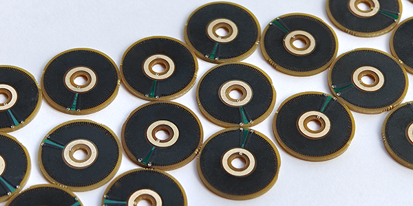
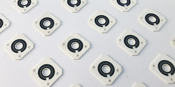
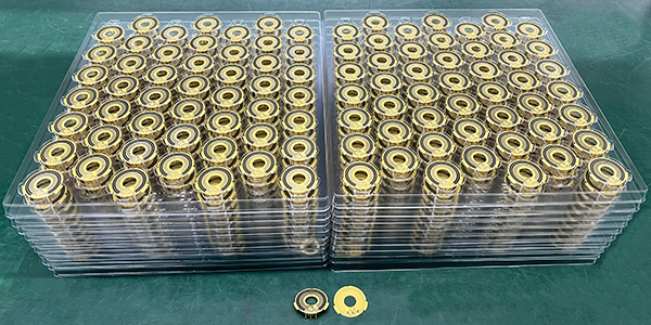
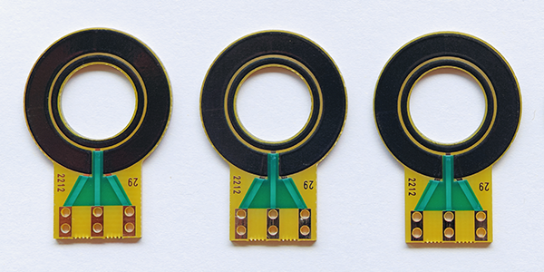
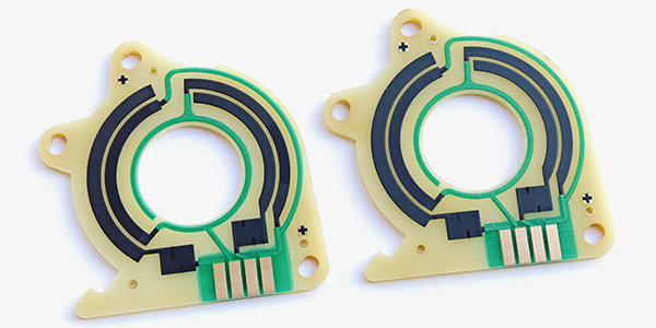
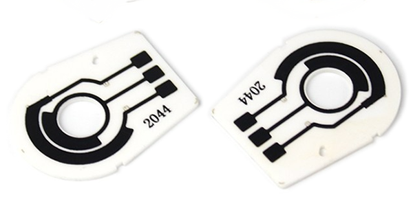
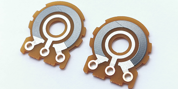
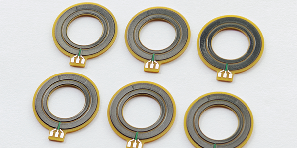
Rotary Potentiometer Carbon Track PCB
Rotary Potentiometer Carbon Track PCBs, also called Rotary Potentiometer Carbon PCBs, serve as variable resistor elements, enabling users to adjust resistance and control voltage outputs through rotational motion, consisting of a conductive carbon track printed onto a PCB substrate with a wiper that moves along the track as the knob is rotated to create a variable voltage divider, where the wiper's position determines the resistance value for precise electrical control, while also offering linear or logarithmic resistance changes, making them versatile for applications like audio volume control and precision measurement devices.
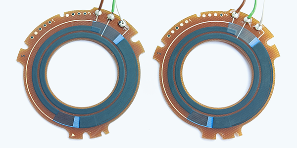
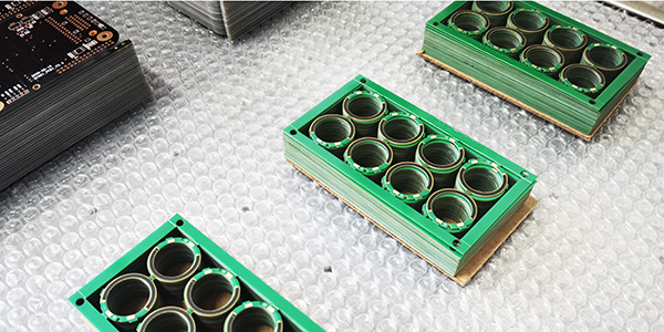
Rotary Potentiometer Carbon Track PCBs are manufactured using thick-film technology, where carbon-based resistive material is screen-printed onto a substrate, ensuring precise patterning. Designed for smooth interaction between the resistive track and the wiper, they ensure reliable performance. Throughout production, strict quality control is applied to ensure that each component meets the required specifications for durability, accuracy, and consistency, ensuring high reliability in real-world applications.
Rotary Potentiometer Carbon PCBs are widely used in audio devices, providing smooth and reliable volume control. They are also found in household appliances like light dimmers and fans, enabling users to regulate power or speed. In industrial control systems, they offer precise adjustments for machinery and equipment, and their durability makes them ideal for consumer electronics, scientific instruments, and applications that require frequent use and high reliability.
Applications of Rotary Potentiometer Carbon Track PCB :
Rotary Potentiometer Carbon Track PCBs are essential components in various industries, offering adjustable resistance through rotational motion. Here are some key applications:
● Audio Control: Used in audio equipment for adjusting volume or tone, such as in stereo audio control.
● Automotive and Motorcycle Applications: Used in automobiles for headlight positioning sensors, gear shifting, steering angle measurement, suspension, and throttle control.
● Industrial Equipment: Found in industrial control equipment such as injection molding machines, generators, welders, and valves for precise control.
● Agricultural and Heavy Machinery: Used in agricultural machinery and heavy equipment for monitoring and controlling equipment position and speed.
● Home Appliances: Used in home appliances such as ovens and microwaves for temperature control, Also in fans and lighting equipment for speed control and dimming.
● Medical Devices: Used in medical devices for precise adjustment of equipment settings.
● Robotics: Used in robotics for controlling the angle of robotic arms or the speed of wheeled robots.
● Industrial Automation: Used in industrial automation machinery, such as automated control systems.
● Communication Equipment: Used in communication equipment for adjusting signal strength.
● Precision Measurement: Used in precision measurement equipment for calibration and adjustment of measurement parameters.
● Servo Motor Control: In some applications, such as audio equipment, rotary potentiometers can be combined with servo motors to achieve a combination of automatic and manual adjustments.
These applications demonstrate the versatility and reliability of the Rotary Potentiometer Carbon Track PCBs, making it an ideal choice for electrical systems that require precise control and adjustment.
Advantages of Rotary Potentiometer Carbon Track PCB :
Rotary Potentiometer Carbon Track PCBs, produced using thick film resistor technology on a printed circuit board, offers several advantages from a manufacturing perspective:
● High Precision: Precise screen printing and laser trimming techniques enable fine adjustments of resistance values, ensuring the accuracy and stability of the potentiometer.
● High Durability: The carbon track's resistance to wear is superior to many traditional resistive materials and with high-temperature sintering, providing the Rotary Potentiometer Carbon Track PCB with a longer service life.
● Excellent Linearity: The change in resistance is linearly related to the rotation angle, offering users a consistent and accurate variation in resistance.
● Temperature Stability: Thick-film resistive technology allows the potentiometer to maintain stable resistance values across a wide temperature range.
● Miniaturization: Rotary Potentiometer Carbon Track PCBs can be designed to be very compact, making it suitable for applications with space constraints.
● Cost-Effective: Compared to many traditional potentiometers, thick-film technology can reduce manufacturing costs and enable mass production.
● Good Resolution: Rotary Potentiometer Carbon Track PCBs can achieve very smooth and continuous resistance changes, making it suitable for applications that require fine adjustments.
● Environmental Adaptability: The chemical stability of thick-film resistive materials allows the potentiometer to operate in harsh environments.
● Flexible Design: Rotary Potentiometer Carbon Track PCBs can be customized to meet different application needs in terms of resistance value, rotation angle, and circuit patterns.
● Easy Integration: It can be manufactured directly on the PCB, simplifying the assembly process and improving production efficiency.
Rotary Potentiometer Carbon Track PCBs utilizing thick-film resistive technology, achieves high precision, high durability, and excellent temperature stability, making them ideal for applications that require precise control.
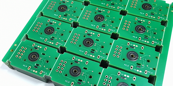
Material Selections of Rotary Potentiometer Carbon PCB :
When manufacturing Rotary Potentiometer Carbon PCBs, the common substrate materials include FR4, Ceramic, and Flexible PI. Here's a comparative introduction to the advantages and disadvantages of these three substrate materials:
1, FR4 Potentiometer Carbon PCBs :
Advantages:
● Cost-Effectiveness: FR4 is the most common PCB substrate material, and due to its widespread use, it is relatively low in cost.
● Good Electrical Properties: FR4 has good insulation and mechanical strength, making it suitable for most electronic applications.
● Easy to Process: FR4 is easy to manufacture and fabricate, compatible with various PCB production techniques.
Disadvantages:
● Limited Heat Resistance: Although FR4 can operate at higher temperatures, it has lower heat resistance compared to ceramic substrates.
● Relatively High CTE: This can affect the stability of the circuit under temperature changes.
2, Ceramic Potentiometer Carbon PCBs :
Advantages:
● High Thermal Conductivity: Ceramic substrates have excellent thermal conductivity, which is helpful for heat dissipation and suitable for high-power applications.
● Good Electrical Insulation: Ceramic materials have high electrical insulation properties, making them ideal for high-frequency circuits.
● Thermal Stability: Ceramics have a low coefficient of thermal expansion, making them suitable for operation under extreme temperatures.
Disadvantages:
● Higher Cost: Compared to FR4, ceramic substrates are more expensive.
● Processing Difficulty: Due to the high hardness of ceramic materials, they are more difficult and costly to process.
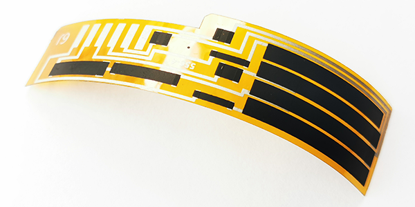
3, Flexible PI Potentiometer Carbon PCBs :
Advantages:
● Flexibility: PI substrates have good flexibility, making them suitable for applications that require bending or curling.
● High-Temperature Resistance: PI substrates can operate stably in high-temperature environments.
● Chemical Resistance: PI substrates have good resistance to a variety of chemicals.
Disadvantages:
● Higher Cost: The cost of PI substrates is usually higher than that of FR4.
● Electrical Properties: Although PI substrates have excellent mechanical properties, their electrical properties may not be as good as those of ceramic substrates.
When selecting a substrate material for Rotary Potentiometer Carbon PCBs, it is necessary to balance the specific requirements of the application and the budget. For instance, if the application requires high power handling and excellent heat dissipation, ceramic might be a better choice. If considering a balance between cost and electrical performance, FR4 might be a more suitable choice. For applications requiring flexibility, PI substrates are the ideal choice.
Main Types of Potentiometer Carbon PCB :
Potentiometer Carbon PCBs developed based on thick film resistor technology has two common types:
● Linear Potentiometer Carbon Track PCB.
● Rotary Potentiometer Carbon Track PCB.
The main difference between these two common types of potentiometer PCBs lies in their adjustment methods and application scenarios. Linear potentiometers are typically used where precise and predictable adjustments are needed, while Rotary Potentiometers are better suited for applications requiring continuous and smooth adjustments.
1, Linear Potentiometer Carbon Track PCB :
● Resistance Variation Pattern: The resistance change of a linear potentiometer is linearly related to the angle of its movement or rotation. This means that as the wiper or knob of the potentiometer moves, the resistance value changes uniformly, and the output voltage is proportional to the rotation angle or sliding distance.
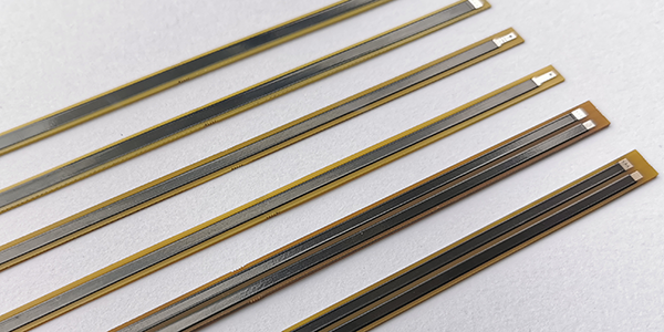
● Adjustment Method: Linear potentiometers can be single-turn or multi-turn. A single-turn potentiometer returns to its starting position after one or several rotations, while a multi-turn potentiometer can continuously rotate multiple turns, providing finer adjustments.
● Functionality: The resistance value of a linear potentiometer changes linearly with the position of its wiper, offering voltage or resistance changes that are proportional to the wiper's position. This characteristic makes linear potentiometers ideal for applications requiring precise control of voltage or current.
● Applications: They are commonly used in electronic devices for volume control, analog signal adjustment, instrument calibration, and any scenario requiring linear adjustments. For instance, in audio systems, linear potentiometers can control the gain of signals, or they can be used in precision measuring devices to adjust measurement parameters.
2, Rotary Potentiometer Carbon Track PCB :
● Resistance Variation Pattern: The resistance change of a rotary potentiometer can be linear, logarithmic, or exponential, depending on the design of the potentiometer. For example, a logarithmic potentiometer (Type C) experiences smaller resistance changes at the beginning of rotation, while the resistance change becomes larger as it approaches the maximum resistance end.
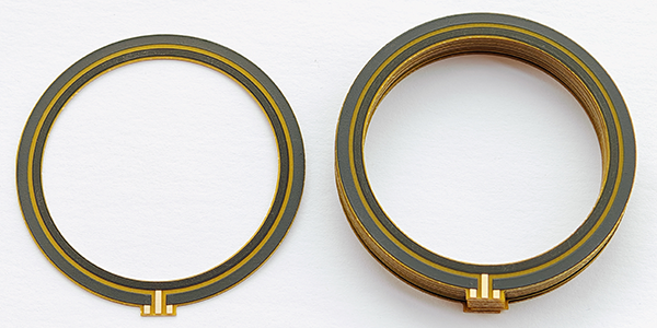
● Adjustment Method: Rotary potentiometers change their resistance values through a rotational action, commonly used to obtain adjustable power supply voltages for certain electronic circuits.
● Functionality: Rotary potentiometers adjust their resistance values through rotation, typically used in applications requiring continuous adjustments. They can be linear or logarithmic (where the resistance change corresponds exponentially to the rotation angle), depending on their design and purpose.
● Applications: Rotary potentiometers are widely used in communication devices, car audio systems, household appliances, and medical equipment, where continuous adjustment is needed. For example, in car audio systems, rotary potentiometers can adjust volume or balance. Additionally, they are often used in industrial control and instrument calibration, where non-linear adjustments may be required, such as temperature or pressure control.
Linear Potentiometers provide uniform resistance changes suitable for precise adjustments, while Rotary Potentiometers offer continuous adjustments suitable for smooth control applications.
Process Capabilities of Rotary Potentiometer Carbon PCB :
Items |
Typical Values |
1, Substrates : |
FR4, Alumina ( Ceramic), Polyimide (Flexible PCB), Stainless Steel (SUS304), Mica |
2, Conductors Material : |
Copper, Silver , Gold , Silver-Palladium, Palladium-Gold |
3, Thick Film Carbon Thickness (height) : |
15um +/-5 um |
4, Silver Palladium Thickness (height) : |
12um+/-5um |
5, Minimum Width of Thick Film Traces : |
0.25 mm +/-0.05 mm |
6, Minimum Spacing of Thick Film Traces : |
0.25 mm +/-0.05 mm |
7, Minimum Footprint (Carbon to Copper) : |
No less than 0.20mm |
8, Sheet Resistivity (ohms/square): |
Printed resistors in milli ohm to mega ohm range (Customizable) with tolerances of 1-10% are fabricated and protected with overglaze materials |
9, Resistor Value Tolerance : |
+/-10.0% (Standard) (Customizable) |
10, Linearity : |
+/-1.0% (Standard) (Customizable) |
11, Synchronism of Potentiometers (Double Channels) : |
+/-2.0% (Standard) (Customizable) |
12, Durability of Carbon Ink (Life time) : |
0.5 Million (Min), 2.0-5.0 Million (Standard) |
13, Working Temperature : |
- 40℃ /+150℃ |
For more information, Please refer to Thick Film Potentiometer PCB.
Custom Thick Film Sensors
- Custom Thick Film Sensor Elements
- Fuel Level Sensor PCB
- Fuel Level Sensor Ceramic PCB
- Oil Level Sensor Ceramic PCB
- Motorcycle Fuel Level Sensor PCB
- Throttle Position Sensor PCB
- Throttle Position Sensor FR4 PCB
- Throttle Position Sensor Ceramic PCB
- Throttle Position Sensor Flexible PCB
- Accelerator Pedal Sensor PCB
- Accelerator Pedal Position Sensor PCB
- Pedal Position Sensor Carbon PCB
- Potentiometer PCB
- Linear Potentiometer Carbon Track PCB
- Rotary Potentiometer Carbon Track PCB
- FR4 Potentiometer Carbon PCB
- Ceramic Potentiometer Carbon PCB
- Flexible Potentiometer Carbon PCB
- Logarithmic Taper Potentiometer PCB
- Position Sensor PCB
- FR4 Position Sensor Carbon PCB
- Ceramic Position Sensor Carbon PCB
- Flexible Position Sensor Carbon PCB
- Flexible Sensor PCB
- Printed Flexible Electronic PCB
- Printed Carbon PCB
- Ceramic Pressure Sensors
- Ceramic Thick Film Pressure Sensors
- Engine Oil Pressure Sensor PCB
- Gold Coated Ceramic Substrates
- Gold Coated Thick Film Substrates
- Metallized Ceramic Substrates
- Multilayer Thick Film Substrates
- Thick Film Metallization Technology
- Thin Film Metallization Technology
- Thin Film Ceramic PCB
- Variable Resistor Carbon PCB
- Remote Ready Sender Ceramic PCB
- LP Gas Tank Gauges Ceramic PCB
- Thick Film Capacitive Sensors
- Thick Film Capacitive Pressure Sensors
- Thick Film Edible Oil Quality Sensors
- Thick Film Meteorological Rainfall Sensors
- PI Interdigital Electrodes (Flexible)
- Air Door Actuator PCB
- HVAC Blend Door Actuator PCB