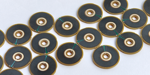
Logarithmic Taper Potentiometers PCB
Logarithmic Taper Potentiometer PCBs, also called Non-Linear Potentiometer PCBs, are designed to offer resistance changes that follow a logarithmic scale, making them ideal for applications where adjustments mirror human sensory perception, particularly in audio devices. Unlike linear potentiometers, which change resistance uniformly, logarithmic potentiometers provide a more natural and smooth volume control experience, aligning with the way we perceive sound intensity, making them particularly suited for applications such as volume control, audio signal fade-in/fade-out, and balance adjustments where users require fine-tuned, intuitive control over audio signals.
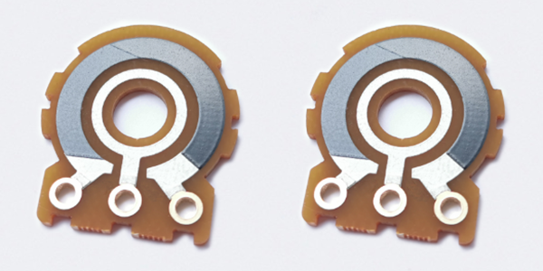
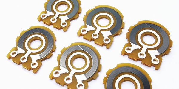
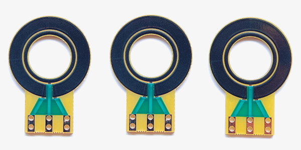
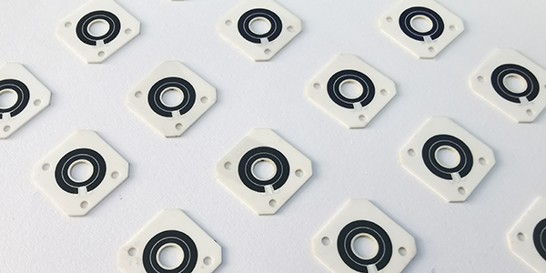
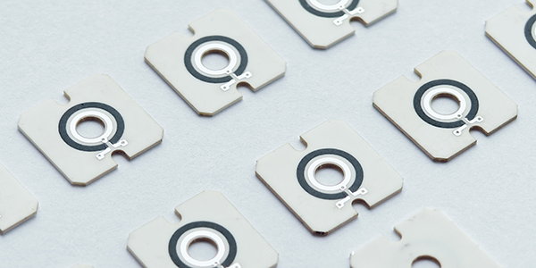
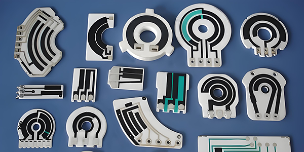
Logarithmic Taper Potentiometer PCBs are manufactured using thick film resistor technology. In this process, a resistor paste is screen-printed onto substrates such as FR4 or ceramic, followed by high-temperature sintering to form a resistive layer. This layer is then precisely trimmed using laser technology to ensure accurate resistance values. The manufacturing method ensures that the potentiometers are highly accurate and reliable, capable of withstanding varying conditions in sensitive electronic applications. The integration of these components onto a single PCB also streamlines production and reduces the need for external components.
Logarithmic Potentiometer PCBs are recognized for their nonlinear resistance changes, which are ideal for applications requiring smooth, intuitive adjustments. These potentiometers closely mimic human auditory perception, offering a more natural response compared to linear alternatives. They are highly accurate and durable, with thick film resistor technology contributing to their robustness and long lifespan. Additionally, their compact design allows for seamless integration into circuits, reducing the overall complexity of the system. This makes them a reliable and efficient choice for a wide range of applications where precise control over analog signals is required.
Logarithmic Potentiometer PCBs are widely used in audio equipment, such as volume controls, audio equalizers, mixers, and other sound management devices, where precise control over sound signals is crucial. Their logarithmic resistance change makes them ideal for creating a more natural volume adjustment experience in audio devices. Beyond audio equipment, these potentiometers are also employed in industrial control systems and other applications where accurate signal adjustment is necessary. Their versatility and reliability make them an essential component in systems that demand fine-tuned, user-friendly control over analog signals.
Features of Logarithmic Taper Potentiometer PCB :
Logarithmic Taper Potentiometer PCBs (Printed Circuit Boards) are specially designed circuit boards intended for mounting logarithmic taper potentiometers.
● Logarithmic Potentiometer Installation: Logarithmic Taper Potentiometer PCBs are equipped with logarithmic taper potentiometers, which have resistance values that change according to a logarithmic scale. This feature makes them particularly suitable for applications such as volume control, where human auditory perception is logarithmic.
● Circuit Design: Circuit design on logarithmic taper potentiometer PCBs takes into account the unique characteristics of these potentiometers, such as resolution, end-to-end resistance, and compatibility with other electronic components. This ensures optimal performance and functionality.
● Digital Interfaces: Some logarithmic taper potentiometer PCBs may incorporate digital interfaces, such as SPI (Serial Peripheral Interface) or I2C (Inter-Integrated Circuit), enabling precise control and easier integration with microcontrollers and digital systems.
● Non-volatile Memory: Logarithmic Taper Potentiometer PCBs may also integrate non-volatile memory to retain the potentiometer's settings even when power is turned off. This feature is particularly useful in applications where settings need to be preserved.
● Temperature Compensation: Logarithmic taper potentiometer PCBs may include temperature compensation mechanisms to ensure stable performance across varying temperature conditions. This helps maintain accuracy and reliability.
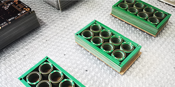
● Multiple Packaging Options: These Logarithmic Taper Potentiometer PCBs often provide various packaging options to accommodate different applications and space requirements, offering flexibility in design and implementation.
● Low Power Design: Many logarithmic taper potentiometer PCBs are designed with low power consumption in mind, reducing energy usage and extending the lifespan of the device.
● High Reliability: The design of logarithmic taper potentiometer PCBs emphasizes high reliability, including durability and data retention time, to ensure consistent operation over time.
● Wide Applications: Logarithmic taper potentiometer PCBs find extensive use in fields such as audio equipment, medical devices, and industrial control systems, particularly in applications requiring logarithmic response characteristics.
● Anti-aliasing Filters: In some designs, logarithmic taper potentiometer PCBs may incorporate anti-aliasing filters to enhance the performance of conversion responses, further improving signal quality.
These features make logarithmic taper potentiometer PCBs an ideal choice for achieving precise control and adjustment, especially in audio applications where simulating the human ear's perception of sound is critical.
Non-Linear Potentiometer PCB in Audio Equipments :
● Volume Control: Logarithmic potentiometers are designed to change their resistance according to a logarithmic scale, which aligns well with the human ear's perception of sound intensity. This characteristic makes them particularly suitable for volume control in audio devices. By using logarithmic potentiometers, users experience a more natural and intuitive adjustment of volume levels, allowing for smooth transitions as they rotate the volume knob.
● Audio Signal Gain Adjustment: In some audio devices, it is necessary to adjust the gain of the audio signal in addition to volume control. Logarithmic potentiometers can be employed for gain control, accommodating variations in the intensity of different audio sources.
● Audio Equalization: In complex audio processing equipment, logarithmic potentiometers can be utilized to adjust the gain across different frequency bands, enabling balanced audio signal processing. This application is particularly common in professional audio equipment, enhancing sound quality and user experience.
● Application of Digital Potentiometers: In digital audio equipment, digital potentiometers facilitate precise volume adjustments and audio balance control. These digital potentiometers feature logarithmic tapers, with a change of 1dB per step, providing accurate volume control and audio signal processing capabilities.
● Mute Functionality: Some digital potentiometers not only offer volume control but also incorporate a mute function, allowing the signal to be attenuated below 90dB for complete silence.
● Zero-Crossing Detection: To minimize audio noise that may occur during volume adjustments, certain digital potentiometers include zero-crossing detection features. This ensures that the potentiometer switches position either at the zero-crossing point of the audio signal or shortly thereafter, reducing unwanted noise.
● Multichannel Audio Devices: In multichannel audio systems, such as stereo or surround sound setups, logarithmic potentiometers can be used to control the volume of multiple channels individually or simultaneously, allowing for balanced sound field adjustments.
● Precise Control of Audio Signals: The application of logarithmic taper potentiometer PCBs in audio devices also encompasses precise control over audio signals. This is particularly evident in digital mixing consoles, audio amplifiers, and audio processing units, where digital control enables fine-tuning of sound signals.
These applications highlight the diversity and importance of logarithmic taper potentiometer PCBs in audio equipment. They not only provide volume control that aligns with human auditory characteristics but also enable complex audio signal processing and adjustments.
Linear Potentiometer VS Logarithmic Potentiometer PCB :
The differences between Logarithmic Potentiometer PCBs and Linear Potentiometer PCBs in practical applications can be highlighted in several key areas:
1, Resistance Variation Characteristics:
● Logarithmic Potentiometer PCB: The resistance value changes according to a logarithmic scale, making it suitable for applications like volume control. This is because the human ear perceives sound intensity logarithmically. Initially, the change in resistance is small as the rotation angle increases, but it becomes more pronounced as the angle continues to increase.
● Linear Potentiometer PCB: The resistance value changes linearly with the rotation angle, making it ideal for applications requiring precise resistance control, such as voltage divider circuits and feedback networks.
2, Application Scenarios:
● Logarithmic Potentiometer PCB: Commonly used in audio devices for volume and tone control, as they provide an adjustment effect that aligns with human auditory characteristics.
● Linear Potentiometer PCB: Suitable for circuits that require uniform voltage regulation, such as precision measuring devices, audio equalizers, and control systems. These applications demand good linearity to ensure accurate control and expected response during adjustments.
3, User Experience:
● Logarithmic Potentiometer PCB: Users perceive volume changes as smoother and more natural because small adjustments in low volume are more easily detectable compared to those at high volume levels.
● Linear Potentiometer PCB: In applications requiring precise control, users can expect a direct proportional relationship between the rotation angle and the output change, making it ideal for adjustments in voltage division and monotonic control.
4, Technical Implementation:
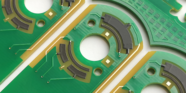
● Logarithmic potentiometer PCB: Special design is required to achieve logarithmic characteristics, such as using segmented printing technology to connect two different resistance materials (carbon paste) together.
● Linear potentiometer PCB: The design is relatively simple, and the conductive material on the resistance element is evenly distributed, with approximately equal resistance per unit length.
5, Performance Requirements:
● Logarithmic Potentiometer PCB: In audio equipment, logarithmic potentiometers provide volume control that aligns more closely with human hearing characteristics, enhancing sound quality and user experience.
● Linear Potentiometer PCB: In systems that require precise control, linear potentiometers deliver stable and predictable resistance changes, ensuring system performance and stability.
The choice between logarithmic potentiometer PCBs and linear potentiometer PCBs depends on specific application requirements and the desired user experience. Logarithmic potentiometer PCBs are better suited for audio applications that mimic human sound perception, while linear potentiometer PCBs are ideal for applications needing precise and linear control.
Process Capabilities of Potentiometer PCB :
Items |
Typical Values |
1, Substrates : |
FR4, Alumina (Ceramic), Polyimide (Flexible PCB), Stainless Steel (SUS304), Mica |
2, Conductors Material : |
Copper, Silver , Gold , Silver-Palladium, Palladium-Gold |
3, Thick Film Carbon Thickness (height) : |
15um +/-5 um |
4, Silver Palladium Thickness (height) : |
12um+/-5um |
5, Minimum Width of Thick Film Traces : |
0.25 mm +/-0.05 mm |
6, Minimum Spacing of Thick Film Traces : |
0.25 mm +/-0.05 mm |
7, Minimum Footprint (Carbon to Copper) : |
No less than 0.20mm |
8, Sheet Resistivity (ohms/square): |
Printed resistors in milli ohm to mega ohm range (Customizable) with tolerances of 1-10% are fabricated and protected with overglaze materials |
9, Resistor Value Tolerance : |
+/-10.0% (Standard) (Customizable) |
10, Linearity : |
+/-1.0% (Standard) (Customizable) |
11, Synchronism of Potentiometers (Double Channels) : |
+/-2.0% (Standard) (Customizable) |
12, Durability of Carbon Ink (Life time) : |
0.5 Million (Min), 2.0-5.0 Million (Standard) |
13, Working Temperature : |
- 40℃ /+150℃ |
For more information, Please refer to Thick Film Potentiometer PCB.
Custom Thick Film Sensors
- Custom Thick Film Sensor Elements
- Fuel Level Sensor PCB
- Fuel Level Sensor Ceramic PCB
- Oil Level Sensor Ceramic PCB
- Motorcycle Fuel Level Sensor PCB
- Throttle Position Sensor PCB
- Throttle Position Sensor FR4 PCB
- Throttle Position Sensor Ceramic PCB
- Throttle Position Sensor Flexible PCB
- Accelerator Pedal Sensor PCB
- Accelerator Pedal Position Sensor PCB
- Pedal Position Sensor Carbon PCB
- Potentiometer PCB
- Linear Potentiometer Carbon Track PCB
- Rotary Potentiometer Carbon Track PCB
- FR4 Potentiometer Carbon PCB
- Ceramic Potentiometer Carbon PCB
- Flexible Potentiometer Carbon PCB
- Logarithmic Taper Potentiometer PCB
- Position Sensor PCB
- FR4 Position Sensor Carbon PCB
- Ceramic Position Sensor Carbon PCB
- Flexible Position Sensor Carbon PCB
- Flexible Sensor PCB
- Printed Flexible Electronic PCB
- Printed Carbon PCB
- Ceramic Pressure Sensors
- Ceramic Thick Film Pressure Sensors
- Engine Oil Pressure Sensor PCB
- Gold Coated Ceramic Substrates
- Gold Coated Thick Film Substrates
- Metallized Ceramic Substrates
- Multilayer Thick Film Substrates
- Thick Film Metallization Technology
- Thin Film Metallization Technology
- Thin Film Ceramic PCB
- Variable Resistor Carbon PCB
- Remote Ready Sender Ceramic PCB
- LP Gas Tank Gauges Ceramic PCB
- Thick Film Capacitive Sensors
- Thick Film Capacitive Pressure Sensors
- Thick Film Edible Oil Quality Sensors
- Thick Film Meteorological Rainfall Sensors
- PI Interdigital Electrodes (Flexible)
- Air Door Actuator PCB
- HVAC Blend Door Actuator PCB