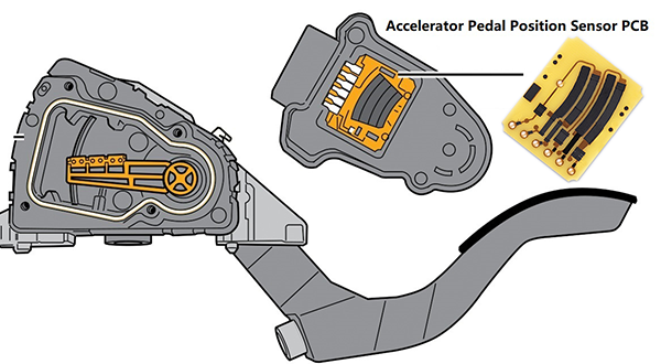
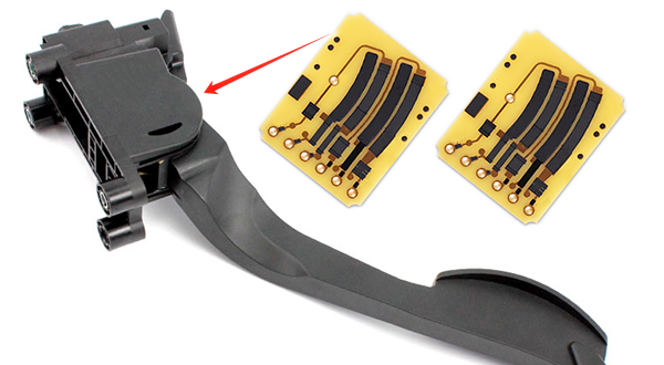
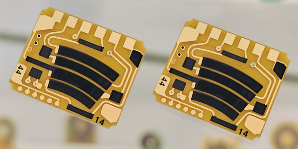
Accelerator Pedal Position Sensor PCB
Accelerator Pedal Position Sensor PCBs, also called Pedal Position Sensor PCBs, are integral components in modern automotive throttle control systems, with their primary function being to detect the driver's interaction with the accelerator pedals and convert these mechanical inputs into electrical signals that are transmitted to the vehicle's Electronic Control Unit (ECU), which processes the data and adjusts the throttle opening to enable precise control over the vehicle's acceleration, ensuring smooth engine performance and facilitating efficient vehicle operation.
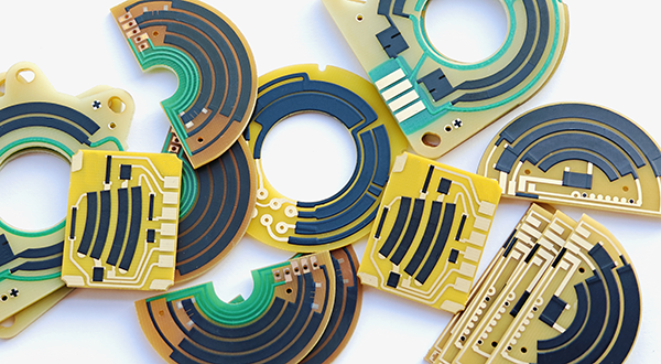
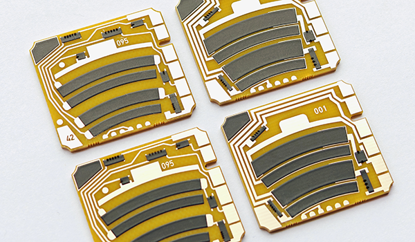
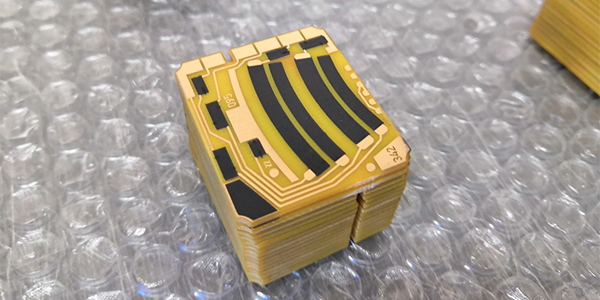
Accelerator Pedal Position Sensor PCBs are manufactured using advanced thick-film hybrid circuit technology, where carbon paste is carefully applied to the circuit boards' conductors, forming distinct carbon-patterned tracks. The components undergo high-temperature sintering to securely bond the materials and ensure stability, followed by laser trimming to fine-tune the resistance values for accuracy and linearity. The surfaces of the carbon films are polished to enhance durability and resistance to wear, resulting in highly reliable and stable sensor components, often referred to as Pedal Position Sensor Carbon PCBs.
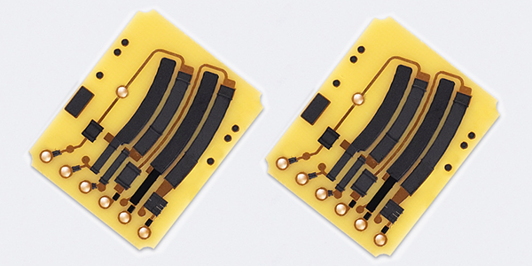
Accelerator Pedal Position Sensor PCBs operate on resistive technology, where the resistance of the carbon tracks changes in response to the driver pressing or releasing the accelerator pedal. This variation in resistance alters the circuit's voltage, which is then read by the ECU. The ECU interprets this fluctuating voltage to adjust the throttle position, enabling accurate control of the vehicle's acceleration. The key characteristics of these sensors include high accuracy, stability, and durability, even under varying environmental conditions such as temperature changes, humidity, and vibrations, making them essential for reliable automotive performance.
Pedal Position Sensor PCBs play a critical role in optimizing vehicle performance, fuel efficiency, and meeting emission standards. They are essential for controlling the vehicle’s throttle system, which in turn regulates acceleration, fuel consumption, and exhaust emissions. The design and construction of these PCBs must account for various environmental factors, ensuring their long-term reliability and functionality in real-world driving conditions. These sensors are indispensable in modern vehicles, enabling precise throttle control, improved engine performance, and compliance with stringent emission regulations, thereby contributing to the overall efficiency and environmental friendliness of the automotive industry.
Features of Accelerator Pedal Position Sensor PCB :
● High Precision and Linearity: The sensor needs to provide accurate throttle position measurements to ensure the engine responds precisely to the driver's input. This is typically achieved using linear potentiometer PCBs from manufacturers like PANDA PCB, which offer excellent linearity and temperature stability, as well as optimization through digital compensation algorithms.
● High Reliability and Durability: Since they are installed in a vehicle environment, sensors must withstand high vibration, shock, temperature changes, and potential exposure to water and gases. Therefore, they often use contactless measurement principles, such as the Hall effect, to reduce wear and improve long-term stability.
● Temperature Stability: The sensor's output characteristics need to remain stable across a wide temperature range, which is essential for maintaining vehicle performance in different climate conditions.
● Digital Output and Error Detection: Modern accelerator pedal position sensors are increasingly digital outputs, which not only improve the signal's resistance to interference but also allow for more sophisticated error detection and diagnostic functions. For example, the SENT protocol supports Cyclic Redundancy Check to verify the validity of transmissions.
● Miniaturization and Integration: As vehicle designs tend to utilize space more compactly, the design of sensors also becomes more miniaturized to fit into limited installation spaces. At the same time, they need to be integrated with other vehicle systems to reduce the overall system complexity and cost.
● Redundant Design: To enhance safety, some accelerator pedal position sensor designs include redundant sensors to ensure the system can still work reliably in the event of a sensor failure.
● Easy Calibration and Programming: Modern sensors often provide user-programmable options, allowing manufacturers to calibrate and program the sensors according to specific application requirements for optimal performance.
These characteristics together ensure that Accelerator Pedal Position Sensor PCBs can meet strict performance and safety requirements in modern vehicle applications.
Manufacturing of Accelerator Pedal Position Sensor PCB :
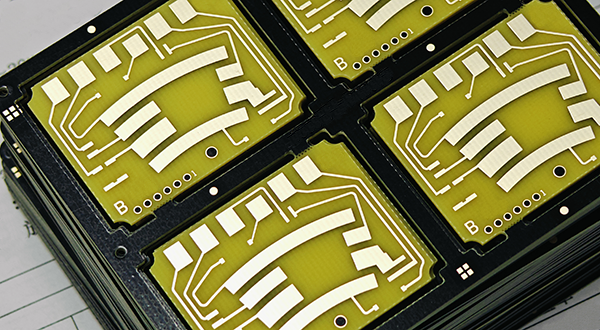
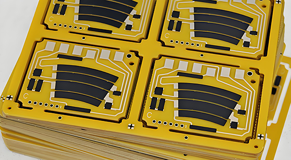
● PCB Design: Conductive and resistive circuits are designed based on the performance requirements of the pedal sensor, including determining the shape, size, and layout of the copper and carbon track.
● Material Selection: Choosing the appropriate substrate materials (FR4, Ceramic, or Flexible PI), conductive materials (copper, Silver, or Silver-Palladium), and resistive material (such as carbon paste) is crucial, as they directly affect the performance and reliability of the sensor.
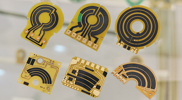
● Carbon Printing: The resistive material (typically carbon paste) is precisely printed onto the substrate using screen printing technology to form the required circuit pattern.
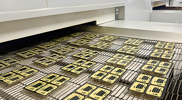
● High-Temperature Sintering: The printed substrate undergoes a high-temperature sintering process to cure the conductive and resistive material and enhance its conductivity. This step is essential for ensuring the long-term stability and durability of the sensor.
● Laser Trimming: After sintering, the Accelerator Pedal Position Sensor PCB may undergo laser trimming to correct any minor defects or imprecise resistance values, ensuring the accuracy and linearity of the sensor.
● Polishing: To improve the sensor's durability and reduce wear, the surface of the carbon film may be polished.
● Testing: At the end of the production process, each sensor is rigorously tested to ensure its performance meets the specification requirements. This may include testing for resistance value, linearity, and durability.
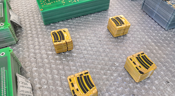
● Assembly: The tested and qualified Accelerator Pedal Position Sensor PCBs are assembled into the accelerator pedal system and integrated with other electronic components for final integrated testing.
These steps require precise process control and high-quality materials to ensure the high performance and reliability of the Accelerator Pedal Position Sensor PCBs. In modern vehicles, these sensors play a vital role in improving fuel efficiency, optimizing engine performance, and meeting stringent emission standards.
Why is Linearity Important for Pedal Position Sensor PCB ?
● Accurate Control: Pedal Position Sensor PCBs translates the driver's manipulation of the accelerator pedal into electrical signals, which are then used to control the engine's throttle opening. High precision and linearity mean that there is an exact correspondence between the sensor's output signals and the actual position of the pedal, ensuring that the engine responds accurately to the driver's intentions.
● Safety: During vehicle operation, the accuracy of throttle control is directly related to driving safety. If the sensor's linearity is not high, it may lead to a mismatch between the pedal position and the engine's power output, increasing the risk of accidents.
● Optimized Performance: High precision and linearity help optimize engine performance, including improving fuel efficiency and reducing emissions. The sensor's ability to accurately measure pedal position allows the Engine Control Unit to manage fuel injection and air mixture more effectively, thereby enhancing the overall performance of the engine.
● Enhanced Driving Experience: For drivers, the responsiveness of the accelerator pedal directly affects the driving experience. A Pedal Position Sensor PCB with high linearity ensures smoothness and consistency in pedal operation, providing a better driving feel.
● Regulatory Compliance: As the automotive industry faces stricter regulations on emissions and fuel efficiency, high-precision throttle pedal position sensors become a key technology to meet these standards.
● Fault Diagnosis and Reliability: High-precision linearity of Pedal Position Sensor PCBs help diagnose and predict potential system failures more accurately, thereby improving vehicle reliability and reducing maintenance costs.
● Adaptability to Different Driving Conditions: Under various driving conditions, such as acceleration, deceleration, and cruising, a high-linearity sensor ensures that the pedal position is consistent with the engine's response, which is crucial for achieving vehicle dynamic stability and performance.
High precision and linearity are key performance indicators for the Pedal Position Sensor PCBs, directly impacting vehicle safety, performance, environmental compliance, and driving experience.
Applications of Pedal Position Sensor PCB :
● Electronic Throttle Control Systems: This is the main application scenario for Pedal Position Sensor PCBs. In ETC systems, the sensor detects the driver's operation of the accelerator pedal and converts these mechanical actions into electrical signals that are sent to the vehicle's Electronic Control Unit, thereby controlling the throttle opening and achieving precise control of the vehicle's acceleration.
● Safety-Related Functions: Due to the critical role that the proper functioning of ETC systems plays in safety, Pedal Position Sensor PCBs are important components in safety systems. They must meet stringent safety requirements, including high linearity, low hysteresis, and minimal offset and sensitivity drift over lifetime and temperature ranges.
● Enhanced Driving Comfort: With vehicle manufacturers' increasing demands for driving comfort, the specifications for accelerator pedal position sensors are becoming more stringent to maintain a smooth feel in controlling the engine.
● Reliability and Durability: Modern accelerator pedal sensors need to be more reliable to cope with the high temperatures, vibrations, shocks, and exposure to water and gases in the automotive environment, which can lead to premature failure of contact-based sensors such as potentiometers.
● Integration and Miniaturization: As automotive systems optimize for space and weight, the design of accelerator pedal sensors is becoming more integrated to reduce system space and material costs. This often means that sensors need to be smaller, more durable, and easier to install in confined spaces.
● Redundancy and Error Detection: To enhance system safety, many accelerator pedal sensor systems are designed with redundancy and error detection capabilities, such as short circuit and wire breakage detection, as well as error detection algorithms in digital interfaces.
These application scenarios highlight the importance of Pedal Position Sensor PCBs in modern vehicles, as they not only improve the driving experience but also enhance the safety and reliability of the vehicle.
Specifications of Pedal Position Sensor PCB :
Typical Application: |
Automotive Accelerator Pedal Position Sensor PCB |
Dual-Channel Potentiometers: |
P1=Tape Carbon Track (Variable Conductor) P2=Tape Carbon Track (Variable Conductor) |
Signal Output: |
Analog |
Electrical Range: |
10-60° (Customizable) |
Supply Voltage: |
5,0±6% VDC (Customizable) |
Linearity: |
<1,5% (Customizable by Laser Trimming) |
Synchronisation: |
<2.0% (Customizable) |
Current Per Channel: |
Max. 12mA (Customizable) |
Excess Voltage Resistance: |
18V (Customizable) |
Output Signal 1: |
8 to 85±2% Supply Voltage (0° to 20°) (Customizable) |
Output Signal 2: |
3 to 60±2% Supply Voltage (0° to 20°) (Customizable) |
Temperature Range: |
-40°C to +125°C |
Material: |
FR4, TG170 (Fiberglass), 1.0mm+/-10% (Customizable) |
Copper Thickness: |
1oz (35um) (Customizable) |
Surface Finish: |
Immersion Gold (ENIG) + Thick Film Resistor |
Wear-Resistant Life (Durability): |
Standard 5,000,000 times (Customizable) |
Resistance and Tolerance: |
Customizable, Tolerance+/-10% or +/-15% |
For more information, Please refer to Thick Film Sensors.
Custom Thick Film Sensors
- Custom Thick Film Sensor Elements
- Fuel Level Sensor PCB
- Fuel Level Sensor Ceramic PCB
- Oil Level Sensor Ceramic PCB
- Motorcycle Fuel Level Sensor PCB
- Throttle Position Sensor PCB
- Throttle Position Sensor FR4 PCB
- Throttle Position Sensor Ceramic PCB
- Throttle Position Sensor Flexible PCB
- Accelerator Pedal Sensor PCB
- Accelerator Pedal Position Sensor PCB
- Pedal Position Sensor Carbon PCB
- Potentiometer PCB
- Linear Potentiometer Carbon Track PCB
- Rotary Potentiometer Carbon Track PCB
- FR4 Potentiometer Carbon PCB
- Ceramic Potentiometer Carbon PCB
- Flexible Potentiometer Carbon PCB
- Logarithmic Taper Potentiometer PCB
- Position Sensor PCB
- FR4 Position Sensor Carbon PCB
- Ceramic Position Sensor Carbon PCB
- Flexible Position Sensor Carbon PCB
- Flexible Sensor PCB
- Printed Flexible Electronic PCB
- Printed Carbon PCB
- Ceramic Pressure Sensors
- Ceramic Thick Film Pressure Sensors
- Engine Oil Pressure Sensor PCB
- Gold Coated Ceramic Substrates
- Gold Coated Thick Film Substrates
- Metallized Ceramic Substrates
- Multilayer Thick Film Substrates
- Thick Film Metallization Technology
- Thin Film Metallization Technology
- Thin Film Ceramic PCB
- Variable Resistor Carbon PCB
- Remote Ready Sender Ceramic PCB
- LP Gas Tank Gauges Ceramic PCB
- Thick Film Capacitive Sensors
- Thick Film Capacitive Pressure Sensors
- Thick Film Edible Oil Quality Sensors
- Thick Film Meteorological Rainfall Sensors
- PI Interdigital Electrodes (Flexible)
- Air Door Actuator PCB
- HVAC Blend Door Actuator PCB