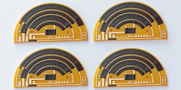
Throttle Position Sensor FR4 PCB
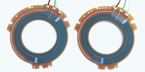
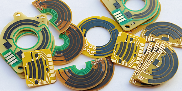
Throttle Position Sensor FR4 PCBs, also called TPS FR4 PCBs, are produced using thick-film hybrid circuit technology that deposits conductive carbon and other materials onto an FR4 substrate, a glass-reinforced epoxy laminate known for its excellent mechanical strength, electrical insulation, and flame retardancy, making it highly suitable for demanding automotive environments exposed to high temperatures, vibrations, and stresses while ensuring precise and reliable component deposition to enhance the sensor's overall performance and durability.
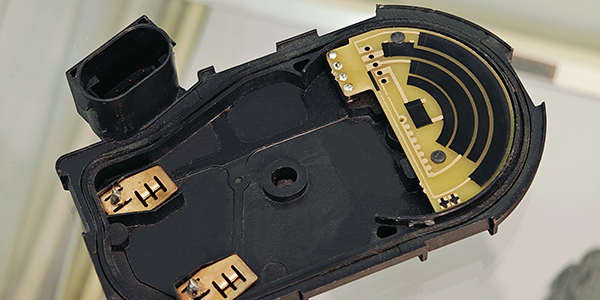
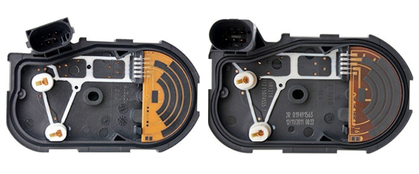
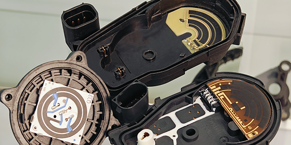
Throttle Position Sensor FR4 PCBs play a critical role in automotive electronics, specifically in the throttle position sensor (TPS). The TPS is essential for providing the engine control unit (ECU) with accurate data regarding the position of the throttle valve. This information is crucial for the ECU to adjust various engine parameters, such as fuel delivery, ignition timing, and engine load. By monitoring the throttle position, the FR4 PCB ensures smooth engine performance, optimal fuel efficiency, and compliance with emission standards. Without accurate throttle position data, the engine's performance would be unpredictable and inefficient.
TPS FR4 PCBs offer several notable features that make them ideal for automotive applications. The FR4 material provides excellent durability and resistance to high temperatures, mechanical stress, and environmental factors, ensuring the sensor's longevity in harsh conditions. Additionally, the thick-film technology used in their production enhances the precision of the sensor's measurements, ensuring reliable data transmission to the ECU. These PCBs are also designed for high reliability and stability, crucial for maintaining optimal engine performance and contributing to fuel efficiency and emission control in modern vehicles.
Features of Throttle Position Sensor FR4 PCB :
1, Linearity:
Throttle Position Sensor FR4 PCBs require precise linear output to ensure accurate measurement of the throttle position. The linear variable resistor type throttle position sensor, through the sliding contact of the potentiometer connected to the throttle shaft, can transform the continuous change of the throttle from fully closed to fully open into a voltage signal, thereby achieving precise judgment of engine operating conditions. This linear relationship is crucial for the Engine Control Unit to adjust fuel injection and ignition timing. For example, a linear output type throttle position sensor can output a continuously variable voltage signal according to the change of the throttle opening, and this signal is proportional to the throttle opening, enabling the ECU to precisely control the operation of the engine.
2, Durability:
Throttle Position Sensor FR4 PCBs must be able to work stably for a long time in the harsh automotive environment. FR4 substrate material is widely used in automotive sensor circuit boards because of its good mechanical strength, electrical insulation, and cost-effectiveness. This material can maintain performance in high-temperature, vibration, and chemically corrosive environments, ensuring the long-term stability of the sensor. The design of the circuit board usually takes durability into account, using appropriate surface treatment and packaging technologies to improve its resistance to the environment. For example, the circuit board may use special coatings or packaging materials to protect the circuit from moisture and corrosive substances, thereby improving its durability.
3, Production Process:
High-quality production processes are key to ensuring the linearity and durability of throttle sensor circuit boards. This includes precise printed circuit board manufacturing, strict quality control, and environmental testing. During the production process, precision equipment is used to print circuit patterns, and automated technology is employed to install electronic components.
In addition, a series of tests are carried out, including temperature cycling tests, vibration tests, and durability tests, to ensure that the final product maintains high performance throughout the entire service life of the vehicle.
4, Material Properties:
Throttle Position Sensor FR4 PCBs based on FR4 substrate material usually have a high glass transition temperature (Tg), which means they can remain stable at higher operating temperatures. In addition, FR4 material also has good electrical insulation and mechanical strength, which helps to improve the performance and reliability of the sensor. Throttle Position Sensor FR4 PCBs based on FR4 substrate materials provide key electronic control functions for modern vehicles through their precise linear output and excellent durability.
Advantages of Throttle Position Sensor FR4 PCB :
● High-Temperature Resistance: FR-4 material can maintain its performance in high-temperature environments, making it ideal for automotive sensors that may be exposed to heat.
● High Mechanical Strength: The mechanical strength of FR-4 ensures stability in various environments, providing reliable support for the sensor components.
● Excellent Electrical Insulation: FR-4 offers excellent electrical insulation, ensuring circuit safety and stability, which is crucial for preventing electrical failures in the sensor.
● Cost-Effective: Despite its high performance, FR-4 is relatively low-cost, making it an ideal choice for most electronic designs, including throttle position sensors.
● Wide Range of Applications: FR-4 PCBs are widely used in various electronic devices due to their reliability and performance, including automotive sensors like the TPS.
Substrates Selection of Throttle Position Sensor PCB :
● FR4 Substrates: FR-4 is a glass-reinforced epoxy laminate that offers a good balance of mechanical strength, electrical insulation, and cost-effectiveness. It is the most common type of PCB material used in a wide range of electronic applications due to its versatility and reliability.
● Ceramic Substrates: Ceramic substrates are known for their excellent thermal conductivity, high-temperature resistance, and chemical stability. They are often used in high-frequency and high-power applications where heat dissipation is critical. Ceramic PCBs can also provide better electrical insulation properties than FR-4.
● Flexible PI (Polyimide) Substrates: Flexible PI is a high-performance material with excellent thermal and chemical resistance. It is used in applications requiring flexibility and durability at high temperatures. PI substrates are often found in flexible circuits and high-temperature environments.
The advantages of throttle position sensor FR4 PCBs in automotive applications include their high-temperature resistance, high mechanical strength, excellent electrical insulation, cost-effectiveness, and widespread industry acceptance. These properties make FR4 an ideal choice for the demanding conditions found in automotive electronics.
When comparing FR4 to other substrate materials like Ceramic and Flexible PI (polyimide), Throttle Position Sensor FR4 PCB offers a balance of properties that make it suitable for a broad range of applications. Ceramic substrates are known for their high thermal conductivity and stability at high temperatures, making them ideal for high-power or high-frequency applications. PI, on the other hand, offers flexibility and can withstand high temperatures, making it suitable for flexible circuits and high-temperature environments. FR4 strikes a balance between cost, performance, and versatility, making it a popular choice across various industries, including automotive.
Material Performance of TPS FR4 PCB :
TPS FR4 PCBs' material performance at extreme temperatures is primarily attributed to the inherent characteristics of the FR-4 material, which is a glass fiber reinforced epoxy laminate combining the strength of glass fiber with the electrical insulation properties of epoxy resin, providing a robust and durable substrate. Its flame retardant property ensures stability even at high temperatures, making it critical for many electronic applications.
● High-Temperature Resistance: FR-4 material can maintain its performance in high-temperature environments, making it ideal for high-temperature applications such as power supplies and high-power circuits. Throttle position sensors in automobiles may be exposed to extreme temperature variations, and the high-temperature resistance of FR-4 ensures stable operation under these conditions.
● High Mechanical Strength: Mechanical strength of FR-4 allows it to remain stable in various environments, whether in industrial control equipment or consumer electronics, FR-4 provides reliable support. This is crucial for withstanding vibrations and impacts that may be encountered in automotive environments.
● Excellent Electrical Insulation: FR-4 has excellent electrical insulation properties, ensuring the safety and stability of the circuit. This is essential for preventing short circuits and other electrical failures.
● Cost-Effectiveness: Despite its outstanding performance, FR-4 is relatively low-cost, making it an ideal choice for most electronic designs, balancing high performance with cost control.
When designing TPS FR4 PCBs, the application requirements at extreme temperatures are taken into account. The thickness of the circuit board affects its electrical performance, mechanical strength, and heat dissipation capabilities. For example, thicker PCBs typically offer better insulation but may have slower signal transmission; while thinner PCBs can transmit signals faster but may compromise some insulation properties. Therefore, the thickness of the circuit board is chosen based on its performance requirements in specific applications to ensure optimal performance at extreme temperatures.
TPS FR4 PCBs' material performance at extreme temperatures is primarily attributed to the inherent characteristics of the FR-4 material, which is a glass fiber reinforced epoxy laminate combining the strength of glass fiber with the electrical insulation properties of epoxy resin, providing a robust and durable substrate. Its flame retardant property ensures stability even at high temperatures, making it critical for many electronic applications.
How to Improve the Linearity of TPS FR4 PCB ?
When producing Throttle Position Sensor FR4 PCBs (TPS FR4 PCBs), enhancing linear output is crucial to ensuring that the circuit board can accurately convert throttle position changes into voltage signals, and that this voltage signal is proportional to the throttle's opening degree. Here are some technical methods to improve linear output:
● Accurate Resistive Materials: Utilizing resistive materials with high precision and stability, such as thick-film resistors, ensures that changes in throttle position result in linear resistance changes, thereby providing an accurate voltage signal.
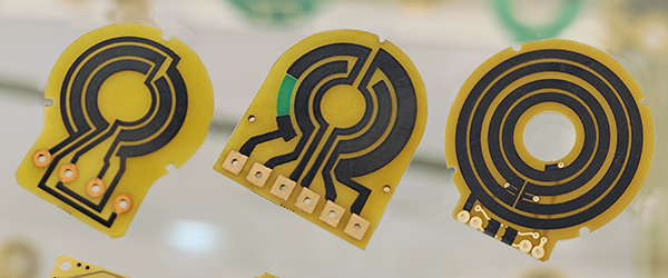
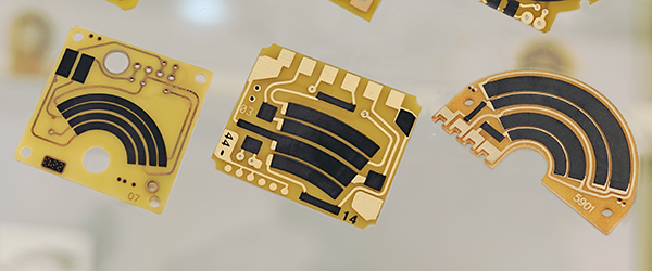
● Refined Circuit Design: The circuit board design should ensure that resistance changes are precisely converted into voltage signals. This includes precise circuit layout and high-quality printed circuit board (PCB) manufacturing processes.
● Calibration and Compensation: Calibrate the sensor during production to ensure that its output signal accurately matches the actual position of the throttle. Additionally, design the circuit to compensate for environmental changes, such as the impact of temperature variations on resistance and voltage output.
● High-Quality Contact Materials: If the sensor is contact-based, using high-quality contact materials reduces wear and maintains long-term linear output.
● Laser trimming Techniques: Employ advanced manufacturing technologies, such as laser cutting and precision printing, to ensure the accuracy and uniformity of the resistive layer.
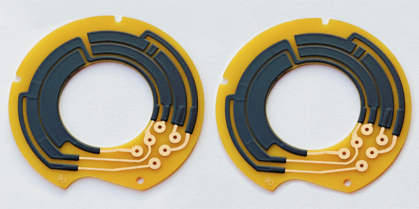
● Redundant Design: In some cases, using two sensors for redundant measurements can improve the system's reliability and accuracy. If one sensor's output deviates, the other sensor's output can be used to correct or verify it.
● Optimized Sensor Structure: Optimize the structural design of the sensor to ensure that the movement of the throttle shaft is accurately converted into resistance or voltage changes.
● Environmental Adaptability Testing: Conduct extensive environmental testing, including temperature, humidity, and mechanical shock tests, to ensure that the sensor maintains linear output under various conditions.
Characteristics of Throttle Position Sensor PCB :
Test Item |
Standard |
Test Method |
Linearity of Output Voltage |
Should be ≤ 1% |
Throttle Position Sensor PCB must maintain a linearity of output voltage that should not exceed ±1% to ensure precise throttle angle measurements. This linearity is tested by recording the sensor's output voltage in relation to the throttle's angular position over multiple full-range cycles. |
Wear Life (Durability) |
Over 5 million cycles |
Throttle Position Sensor PCB utilizes a platinum-palladium alloy wire sliding contact wiper, which ensures durability and reliability. The contact pressure with the resistive body is maintained at 0.15 N ± 0.05 N, and the sensor is designed to endure at least 5 million cycles of operation. |
Temperature Coefficient |
Within specified T.C.R |
Throttle Position Sensor PCB's resistive temperature coefficient is kept within specified limits as per IEC 60115-1 4.8, ensuring stable performance across a range of temperatures from +25°C to -40°C, and up to +125°C. |
Short Time Overload |
(△R/R)≤ 5% |
Throttle Position Sensor PCB is tested for short time overload conditions by applying a voltage of 16V for a period of 60 minutes, ensuring it can handle temporary voltage spikes. |
Rapid Temperature Changing |
(△R/R)≤ 5% |
Throttle Position Sensor PCB is subjected to rapid temperature changes, with cycles of -40°C for 30 minutes, a transition to normal temperature for 5 minutes, and then 125°C for 30 minutes, repeated for 5 cycles. |
Low Temperature Operation |
(△R/R)≤ 5% |
Throttle Position Sensor PCB's low-temperature operation is tested by placing it in a low-temperature chamber at -40°C, maintaining the temperature for 1 hour, and then applying a nominal voltage of (5 ± 0.1) V for 48 hours. |
Endurance at 70°C |
(△R/R)≤ 5% |
Throttle Position Sensor PCB's endurance is evaluated at a constant temperature of 70°C ± 2°C for 1000 hours, with a cycle of 1.5 hours ON and 0.5 hours OFF, using the rated voltage or the limiting element voltage, whichever is lower. |
Damp Heat Steady State |
(△R/R)≤ 5% |
Throttle Position Sensor PCB's performance in damp heat conditions is assessed at 40°C ±2°C and 93% ±3%RH for 1000 hours. |
Low Temperature Storage |
(△R/R)≤ 5% |
Thick Film Resistor is tested for storage at low temperatures of -40°C ±1°C for 1000 hours to ensure long-term stability. |
High Temperature Storage |
(△R/R)≤ 5% |
Thick Film Resistor is also tested for storage at high temperatures of 150°C ±1°C for 1000 hours to evaluate its resistance to prolonged exposure to heat. |
For more information, Please refer to Thick Film Sensors.
Custom Thick Film Sensors
- Custom Thick Film Sensor Elements
- Fuel Level Sensor PCB
- Fuel Level Sensor Ceramic PCB
- Oil Level Sensor Ceramic PCB
- Motorcycle Fuel Level Sensor PCB
- Throttle Position Sensor PCB
- Throttle Position Sensor FR4 PCB
- Throttle Position Sensor Ceramic PCB
- Throttle Position Sensor Flexible PCB
- Accelerator Pedal Sensor PCB
- Accelerator Pedal Position Sensor PCB
- Pedal Position Sensor Carbon PCB
- Potentiometer PCB
- Linear Potentiometer Carbon Track PCB
- Rotary Potentiometer Carbon Track PCB
- FR4 Potentiometer Carbon PCB
- Ceramic Potentiometer Carbon PCB
- Flexible Potentiometer Carbon PCB
- Logarithmic Taper Potentiometer PCB
- Position Sensor PCB
- FR4 Position Sensor Carbon PCB
- Ceramic Position Sensor Carbon PCB
- Flexible Position Sensor Carbon PCB
- Flexible Sensor PCB
- Printed Flexible Electronic PCB
- Printed Carbon PCB
- Ceramic Pressure Sensors
- Ceramic Thick Film Pressure Sensors
- Engine Oil Pressure Sensor PCB
- Gold Coated Ceramic Substrates
- Gold Coated Thick Film Substrates
- Metallized Ceramic Substrates
- Multilayer Thick Film Substrates
- Thick Film Metallization Technology
- Thin Film Metallization Technology
- Thin Film Ceramic PCB
- Variable Resistor Carbon PCB
- Remote Ready Sender Ceramic PCB
- LP Gas Tank Gauges Ceramic PCB
- Thick Film Capacitive Sensors
- Thick Film Capacitive Pressure Sensors
- Thick Film Edible Oil Quality Sensors
- Thick Film Meteorological Rainfall Sensors
- PI Interdigital Electrodes (Flexible)
- Air Door Actuator PCB
- HVAC Blend Door Actuator PCB