Throttle Position Sensor Flexible PCB
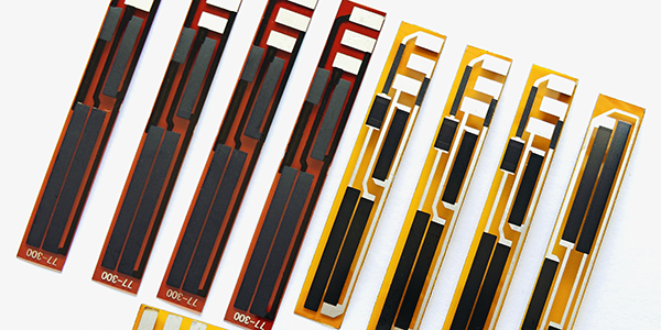
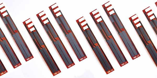
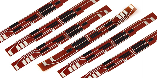
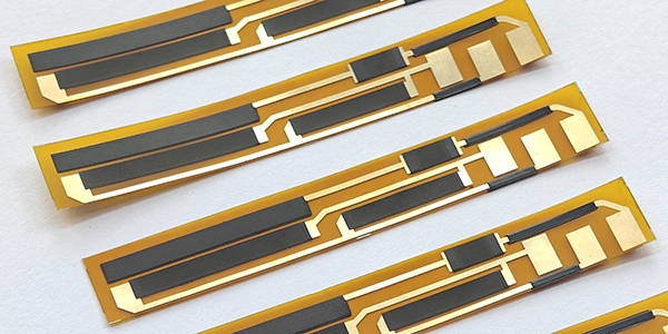
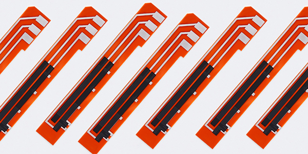
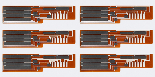
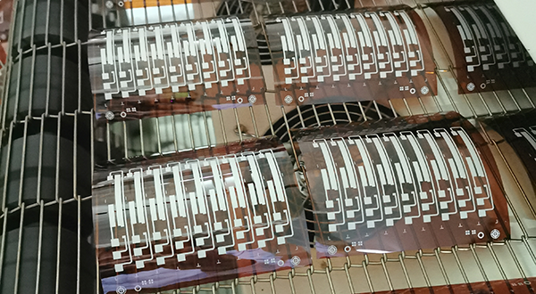
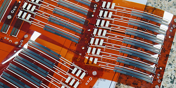
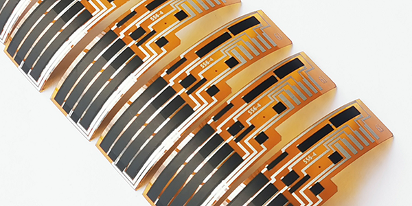
Throttle Position Sensor Flexible PCBs, also called TPS Flexible PCBs, are specialized printed circuit boards designed to monitor the throttle position in automotive engines, playing a crucial role in the engine's electronic control system, and are built using flexible Polyimide (PI) substrates known for their excellent thermal stability, mechanical strength, chemical resistance, and electrical insulating properties, making them highly reliable in harsh automotive environments while offering design flexibility and durability due to the PI material's flexibility.
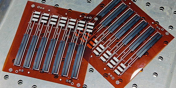
Throttle Position Sensor Flexible PCBs are manufactured using advanced thick-film technology, which allows for the precise printing of carbon and other conductive materials onto the PI substrate. This process ensures that the electrical components within the sensor, such as resistors and conductive paths, are accurately and durably formed. The use of thick-film technology enhances the performance and longevity of the sensor by providing high resistance to mechanical stress, temperature fluctuations, and corrosive elements typically present in automotive applications. This manufacturing method also contributes to the precise control of throttle position data, which is vital for optimizing engine performance.
TPS Flexible PCBs offer several distinct features, including high precision, durability, and reliability in harsh automotive conditions. As a variable resistor, the TPS Flexible PCB adjusts its resistance in response to changes in the throttle's position, generating a corresponding voltage signal for the engine control unit (ECU). The ECU uses this information to regulate fuel injection and engine functions, ensuring optimal performance, fuel efficiency, and compliance with emission standards. These PCBs are integral to the efficient and sustainable operation of modern internal combustion engines.
Features of Throttle Position Sensor Flexible PCB :
● Function: TPS monitors the position of the throttle valve in the engine's intake system. It provides an electrical signal to the engine control unit (ECU) that corresponds to the degree of throttle opening. Throttle Position Sensor Flexible PCB helps the ECU to adjust the air-fuel mixture and ignition timing for optimal engine performance and fuel efficiency.
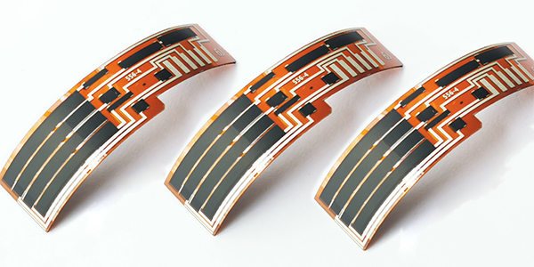
● Construction: Throttle Position Sensor Flexible PCBs are constructed using a Polyimide substrate, which is a high-performance material known for its excellent thermal stability, electrical insulation properties, and resistance to harsh environmental conditions. This makes it ideal for automotive applications where the sensor must withstand high temperatures and vibrations.
● Thick Film Technology: Thick film technology used in the production of the Throttle Position Sensor Flexible PCB allows for the creation of robust and reliable electrical circuits directly onto the PI substrate. This technology involves printing a thick layer of conductive material (like silver or gold) onto the substrate, which is then patterned to form the necessary electrical traces and components.
● Integration: Throttle Position Sensor Flexible PCBs are typically integrated with a potentiometer, which is a type of variable resistor. As the throttle valve moves, it changes the resistance in the potentiometer, which in turn changes the voltage output of the sensor. This voltage signal is then sent to the ECU.
Advantages of Throttle Position Sensor Flexible PCB :
● High-Temperature Resistance: PI material has excellent resistance to high temperatures, making it suitable for sensor circuit boards that operate in high-temperature environments, which helps to improve the durability and reliability of the sensor.
● Chemical Stability: PI material is resistant to a variety of chemicals, allowing the sensor to maintain performance in harsh chemical environments.
● Mechanical Strength: Circuit boards made of PI material have high mechanical strength and can withstand significant mechanical stress, contributing to the sensor's durability.
● Electrical Insulation Properties: PI material circuit boards have good electrical insulation properties, which help to enhance the safety and stability of the sensor.
Challenges of Throttle Position Sensor Flexible PCB :
● Material Cost: The cost of PI material may be higher than traditional circuit board materials, such as Ceramic, FR-4, potentially increasing the overall cost of the sensor.
● Production Complexity: Processing PI material may be more complex than traditional materials, requiring special processes and equipment, which could increase production difficulty and costs.
● Processing Technology Requirements: PI material may require specific processing techniques, such as laser trimming or special lamination techniques, necessitating additional training and capital investment.
● Supply Chain Management: Since PI material may not be as widely available as traditional materials, supply chain management could be more challenging, requiring assurance of material quality and supply stability.
Design Considerations of TPS Flexible PCB :
When designing a TPS Flexible PCB based on polyimide (PI) material, several key electrical design considerations must be taken into account to ensure the performance, reliability, and durability of the circuit board. Here are some of the main considerations:
● Signal Integrity: Ensure that sensor signals are transmitted without interference across the Flexible TPS PCB by designing appropriate routing strategies, including trace width, length, and layer-to-layer layout, as well as possible shielding measures.
● Electromagnetic Compatibility: The design should minimize the generation and susceptibility to electromagnetic interference (EMI), including the use of proper grounding strategies, filters, and shielding.
● Power Management: TPS Flexible PCBs design should include a stable power supply and voltage regulation to ensure the sensor operates reliably under various conditions.
● Thermal Management: Considering the high-temperature resistance of PI material, the design should include effective thermal management strategies, such as heat conduction paths and possible cooling structures.
● Environmental Resistance: TPS Flexible PCBs should be able to withstand vibrations, humidity, temperature changes, and other possible mechanical stresses found in the automotive environment.
● Reliability: Choose high-quality electronic components suitable for automotive applications to ensure the long-term reliability of the circuit board.
● Flexibility: Considering the flexibility of PI material, the design should take into account the circuit board's ability to bend and fold to accommodate different installation spaces and shapes.
● Miniaturization: As automotive electronics become more compact, the circuit board design should be as small as possible without sacrificing performance.
● Cost-Effectiveness: The design should consider cost-effectiveness while meeting all performance requirements, including material selection, manufacturing processes, and assembly.
● Testing and Validation: The design should include testing and validation of the circuit board's performance to ensure it meets all electrical and functional requirements before production.
● Compatibility: TPS Flexible PCBs design should be compatible with other electronic systems in the vehicle, including communication protocols and interface standards.
● Safety: Ensure that the TPS Flexible PCB design complies with automotive industry safety standards, including fault protection and short-circuit protection.
● Material Selection: Choose the appropriate PI material and other auxiliary materials to ensure the electrical and mechanical performance of the circuit board.
● Long-Term Stability: Consider the stability of the TPS Flexible PCB over the long term, including component aging and material performance changes.
Specifications of Throttle Position Sensor Flexible PCB :
● Temperature Rating: Throttle Position Sensor Flexible PCBs should be rated for operation from -40℃ to +125℃, which is typical for automotive applications.
● Material: TPS Flexible PCBs are made from PI (Polyimide), which is known for its high-temperature resistance and chemical stability.
● Layers: Throttle Position Sensor Flexible PCBs may have a single layer, with a thickness of 0.10mm-0.12mm, which is suitable for applications requiring a robust and durable board.
● Surface Treatment: If used copper as conductors, then ENIG (Electroless Nickel Immersion Gold) is a common surface treatment used for its anti-corrosion properties and good solderability.
● Special Processes: Throttle Position Sensor Flexible PCBs are included thick film resistors, which are essential for the sensor's operation, with a resistance value of 2.5 K ohm +/-10% (customizable) and a linearity variation tolerance of less than +/-1.0% (Laser Trimming).
● Substrate Materials: In addition to PI, other substrate materials used for Throttle Position Sensor Flexible PCB, it also can be FR4, Alumina (96%AL2O3), depending on the specific requirements of the application.
● Conductor Material: Copper is commonly used for conductors, and Ag/Pd (Silver Palladium) also can be used for specific applications requiring higher conductivity or resistance to wear.
● Thick Film Thickness: The thickness of the thick film resistor can be 15um +/-5 um, which is critical for the sensor's performance.
● Resistance Range and Tolerance: The resistance range can vary (customizable), but tolerances are typically +/-10%.
● Carbon Ink Durability: The durability of the carbon ink should be at least 5 million cycles to ensure long-term reliability.
Characteristics of Throttle Position Sensor PCB :
Test Item |
Standard |
Test Method |
Linearity of Output Voltage |
Should be ≤ 1% |
Throttle Position Sensor PCB must maintain a linearity of output voltage that should not exceed ±1% to ensure precise throttle angle measurements. This linearity is tested by recording the sensor's output voltage in relation to the throttle's angular position over multiple full-range cycles. |
Wear Life (Durability) |
Over 5 million cycles |
Throttle Position Sensor PCB utilizes a platinum-palladium alloy wire sliding contact wiper, which ensures durability and reliability. The contact pressure with the resistive body is maintained at 0.15 N ± 0.05 N, and the sensor is designed to endure at least 5 million cycles of operation. |
Temperature Coefficient |
Within specified T.C.R |
Throttle Position Sensor PCB's resistive temperature coefficient is kept within specified limits as per IEC 60115-1 4.8, ensuring stable performance across a range of temperatures from +25°C to -40°C, and up to +125°C. |
Short Time Overload |
(△R/R)≤ 5% |
Throttle Position Sensor PCB is tested for short time overload conditions by applying a voltage of 16V for a period of 60 minutes, ensuring it can handle temporary voltage spikes. |
Rapid Temperature Changing |
(△R/R)≤ 5% |
Throttle Position Sensor PCB is subjected to rapid temperature changes, with cycles of -40°C for 30 minutes, a transition to normal temperature for 5 minutes, and then 125°C for 30 minutes, repeated for 5 cycles. |
Low Temperature Operation |
(△R/R)≤ 5% |
Throttle Position Sensor PCB's low-temperature operation is tested by placing it in a low-temperature chamber at -40°C, maintaining the temperature for 1 hour, and then applying a nominal voltage of (5 ± 0.1) V for 48 hours. |
Endurance at 70°C |
(△R/R)≤ 5% |
Throttle Position Sensor PCB's endurance is evaluated at a constant temperature of 70°C ± 2°C for 1000 hours, with a cycle of 1.5 hours ON and 0.5 hours OFF, using the rated voltage or the limiting element voltage, whichever is lower. |
Damp Heat Steady State |
(△R/R)≤ 5% |
Throttle Position Sensor PCB's performance in damp heat conditions is assessed at 40°C ±2°C and 93% ±3%RH for 1000 hours. |
Low Temperature Storage |
(△R/R)≤ 5% |
Thick Film Resistor is tested for storage at low temperatures of -40°C ±1°C for 1000 hours to ensure long-term stability. |
High Temperature Storage |
(△R/R)≤ 5% |
Thick Film Resistor is also tested for storage at high temperatures of 150°C ±1°C for 1000 hours to evaluate its resistance to prolonged exposure to heat. |
For more information, Please refer to Thick Film Sensors.
Custom Thick Film Sensors
- Custom Thick Film Sensor Elements
- Fuel Level Sensor PCB
- Fuel Level Sensor Ceramic PCB
- Oil Level Sensor Ceramic PCB
- Motorcycle Fuel Level Sensor PCB
- Throttle Position Sensor PCB
- Throttle Position Sensor FR4 PCB
- Throttle Position Sensor Ceramic PCB
- Throttle Position Sensor Flexible PCB
- Accelerator Pedal Sensor PCB
- Accelerator Pedal Position Sensor PCB
- Pedal Position Sensor Carbon PCB
- Potentiometer PCB
- Linear Potentiometer Carbon Track PCB
- Rotary Potentiometer Carbon Track PCB
- FR4 Potentiometer Carbon PCB
- Ceramic Potentiometer Carbon PCB
- Flexible Potentiometer Carbon PCB
- Logarithmic Taper Potentiometer PCB
- Position Sensor PCB
- FR4 Position Sensor Carbon PCB
- Ceramic Position Sensor Carbon PCB
- Flexible Position Sensor Carbon PCB
- Flexible Sensor PCB
- Printed Flexible Electronic PCB
- Printed Carbon PCB
- Ceramic Pressure Sensors
- Ceramic Thick Film Pressure Sensors
- Engine Oil Pressure Sensor PCB
- Gold Coated Ceramic Substrates
- Gold Coated Thick Film Substrates
- Metallized Ceramic Substrates
- Multilayer Thick Film Substrates
- Thick Film Metallization Technology
- Thin Film Metallization Technology
- Thin Film Ceramic PCB
- Variable Resistor Carbon PCB
- Remote Ready Sender Ceramic PCB
- LP Gas Tank Gauges Ceramic PCB
- Thick Film Capacitive Sensors
- Thick Film Capacitive Pressure Sensors
- Thick Film Edible Oil Quality Sensors
- Thick Film Meteorological Rainfall Sensors
- PI Interdigital Electrodes (Flexible)
- Air Door Actuator PCB
- HVAC Blend Door Actuator PCB