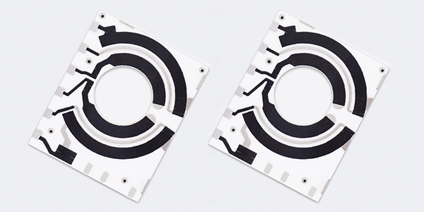
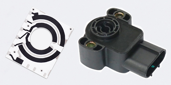
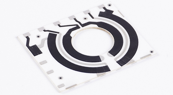
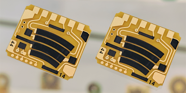
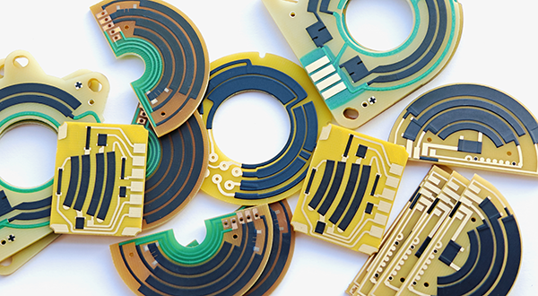
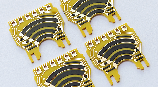
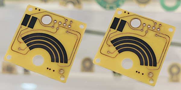
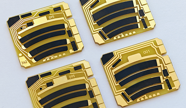
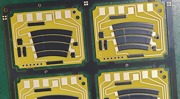
Accelerator Pedal Sensor PCB
Accelerator Pedal Sensor PCBs, also called Accelerator Pedal Module PCBs, are crucial electronic components in modern automotive throttle control systems that convert the mechanical movement of the accelerator pedal into electrical signals by integrating a variable resistor or potentiometer sensor onto the PCB surface, and as the driver presses or releases the accelerator, the position of the pedal changes the resistance within the circuit, generating a corresponding voltage change, which is then transmitted to the vehicle’s electronic control unit (ECU) for processing to adjust the throttle position, enabling precise acceleration control.
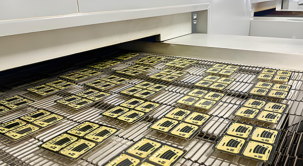
Accelerator Pedal Sensor PCBs are produced using advanced thick-film hybrid circuit technology. Initially, resistive materials are printed onto a substrate, usually made from FR4 or ceramic, in a pre-designed pattern. The PCBs then undergo high-temperature sintering to secure the resistive tracks, ensuring stability and longevity. Laser trimming is applied to finely adjust the resistance values for optimal linearity. The carbon film is polished to enhance its durability, and an insulating resin protective layer is applied to safeguard the sensor from environmental factors such as moisture and temperature fluctuations. These production steps guarantee the performance and reliability of the sensors over time.
Accelerator Pedal Sensor PCBs (APS PCBs) are characterized by their high precision and durability. They rely on resistive technology, where pedal movement alters the resistance, resulting in a proportional voltage change. The sensors are designed to withstand high temperatures, vibrations, and physical wear, making them highly reliable in automotive environments. The insulating resin layer further protects the sensor from harsh conditions, ensuring its continued functionality. These characteristics make Accelerator Pedal Sensor PCBs essential for smooth throttle control, fuel efficiency, and optimal vehicle performance.
Accelerator Pedal Module PCBs (APM PCBs) are integral to electronic throttle control systems, which regulate engine power, fuel consumption, and overall vehicle efficiency. These sensors provide the ECU with accurate data, enabling precise throttle response and preventing unintended acceleration. Accelerator Pedal Sensor PCBs also play a vital role in vehicle safety and performance, contributing to the overall driving experience. Additionally, their ability to enhance fuel efficiency and reduce emissions makes them critical components in modern vehicles, supporting automakers in meeting both environmental and performance standards.
Key Features of Accelerator Pedal Sensor PCB :
● High Precision: Typically, the resistance value tolerance is controllable within ±10%, with linearity <1.0%, ensuring that the Accelerator Pedal Sensor PCBs can accurately detect changes in pedal position and convert these changes into electrical signal output.
● Contact Potentiometers: Accelerator Pedal Sensor PCBs usually employ a contact potentiometer as its operating principle, which detects changes in resistance through physical contact to measure pedal position.
● Temperature Stability: Accelerator Pedal Sensor PCBs can use FR4 or ceramic as the substrate, ensuring that the accelerator pedal sensor PCB operates reliably across a wide temperature range, maintaining stability and accuracy under varying environmental conditions.
● Integration: Accelerator Pedal Sensor PCBs tend toward integrated design, combining communication and signal processing between the sensor and electronic control unit into a single module.
● Environmental Durability: Accelerator Pedal Sensor PCBs can withstand the effects of vibration, humidity, chemicals, and other environmental factors.
● Electromagnetic Compatibility: Due to the presence of many electromagnetic interference sources in the automotive environment, the accelerator pedal sensor PCB possesses good electromagnetic compatibility.
● Miniaturization: With the increasing number of automotive electronic devices, there is a growing demand for efficient use of space, leading to the development of smaller accelerator pedal sensor PCBs to fit limited spaces.
● Good Linearity: Accelerator Pedal Sensor PCBs require to provide good linear output across its entire operating range. Standard manufacturing processes can achieve linearity <1.5%, and for stricter requirements, laser trimming can achieve <0.3%, ensuring an accurate correspondence between the throttle pedal position and the engine throttle opening.
Accelerator Pedal Sensor PCBs possess characteristics that make them a crucial component in automotive electronic systems, particularly in modern vehicles, where they are key to achieving precise electronic throttle control and enhancing driving comfort.
How Durability Important for Accelerator Pedal Sensor PCB ?
Accelerator Pedal Sensor PCBs rely on the durability of the carbon film, which is a critical factor directly affecting the sensor's performance and lifespan, as the carbon film provides a variable resistance when the accelerator pedal is pressed, translating into a signal that the vehicle's engine management system can interpret.
● Longevity and Consistent Performance: A durable carbon film ensures that the sensor can maintain consistent performance over a long period of use. This is crucial in automotive applications where reliability is key.
● Resistance to Wear and Tear: The carbon film is subjected to continuous friction as the pedal is pressed and released. A durable film resists wear, preventing signal degradation and maintaining accuracy in throttle position sensing.
● Environmental Protection: The carbon film is often protected by an insulating resin layer. However, the film itself should also be resistant to environmental factors such as temperature changes, humidity, and exposure to various chemicals. This ensures the sensor's longevity and stability in different operating conditions.
● Linearity and Calibration Stability: A durable carbon film helps maintain the linearity of the sensor's output signal, which is important for accurate throttle control. It also ensures that the sensor's calibration remains stable, reducing the need for frequent recalibrations.
● Reduced Failure Rates: Durability contributes to the overall reliability of the sensor. A sensor with a high-quality, durable carbon film is less likely to fail prematurely, reducing maintenance costs and vehicle downtime.
How To Enhance The Durability for APS PCBs ?
● Use of High-Quality Carbon Paste: Start with a high-quality carbon paste that has excellent conductive properties and durability, and also the base material significantly affects the sensor's longevity and reliability.
● High-Temperature Sintering: The carbon film undergoes a high-temperature sintering process which strengthens the bonds within the carbon structure, resulting in a more robust and durable sensor.
● Polishing the Carbon Film Surface: Polishing the surface of the carbon film can help to reduce friction and wear, thereby enhancing the durability of the sensor. This step can also improve the overall conductivity of the carbon film.
● Quality Control and Testing: Implementing rigorous quality control measures throughout the production process can help to ensure that only sensors that meet the highest standards of durability and performance are released to the market. This includes testing for dimensional accuracy, material strength, and resistance to environmental factors.
● Advanced Material Science: Staying at the forefront of material science research can provide new insights into how the carbon film can be enhanced for greater durability. This might include exploring new types of carbon materials or advanced manufacturing techniques.
By focusing on these strategies above can improve the durability of the carbon film in Accelerator Pedal Sensor PCBs, leading to more reliable and longer-lasting sensors for automotive applications.
Linearity of Accelerator Pedal Sensor PCB :
Accelerator Pedal Sensor PCBs rely on the linearity between the sensor output signal and the position of the accelerator pedal, meaning that any change in pedal position should result in a proportional change in the sensor output signal; this allows the Engine Control Unit to accurately interpret the pedal position and adjust the throttle opening accordingly, enabling precise control of engine acceleration and power output.
● Direct Proportional Relationship: There is a direct proportional relationship between pedal position and sensor output. For example, if the pedal is pressed down 50%, the sensor should output a signal indicating that the throttle should also be opened to 50%.
● Consistency: Throughout the pedal travel, the sensor's output should maintain a consistent linear relationship. This means that whether the pedal is in the starting position, mid-position, or end position, its output signal should follow the same proportional relationship.
● Predictability: Linear sensors provide predictable outputs, allowing the ECU to accurately adjust engine response based on pedal position. This is crucial for driving performance and fuel efficiency.
● Calibration and Adjustment: The linearity of the accelerator pedal sensor can be optimized through calibration and adjustment. This usually involves using precise testing equipment during production to ensure the output signal matches the pedal position accurately.
● Non-Linearity Issues: If the sensor output is not linear, it may lead to inaccurate engine responses, such as jerky acceleration or delayed throttle response. In extreme cases, non-linearity could result in engine failure or safety issues.
● Sensor Types: Accelerator pedal sensors can be contact-based, using potentiometers to directly measure pedal position, or non-contact, using Hall effect sensors or other technologies to indirectly measure pedal position. Regardless of type, it is essential to ensure their output signals exhibit high linearity.
Accelerator Pedal Sensor PCBs achieve linearity through precise control during the design and manufacturing process, including selecting appropriate carbon paste materials, creating accurate printed circuit board layouts, ensuring uniform carbon film thickness, and using processes like laser trimming to control and test the output.
Laser Trimming Linearity For Accelerator Pedal Module PCB :
Accelerator Pedal Module PCBs utilize the laser trimming process during production to precisely adjust resistance values and ensure a linear response of the sensor, using laser technology to finely tune the carbon film traces to match the predetermined resistance values and linear characteristics.
● Laser Ablation: Laser trimming reduces the thickness and width of specific areas of the carbon film by ablating them, thereby changing the resistance value in those areas. Since resistance is inversely proportional to the material's thickness, precise control of the laser ablation's position and extent allows for adjustment of the sensor's resistance output.
● Linear Adjustment: To ensure an accurate linear relationship between the sensor's output signal and pedal position, laser trimming can be used to fine-tune the resistance values of the carbon film. Selective ablation of different parts of the carbon film enables adjustments in the sensor's output at various pedal positions to achieve the desired linear response.
● Precise Control: Laser trimming equipment is typically equipped with high-precision positioning systems that can accurately locate the areas of the carbon film that need adjustment. The size, energy, and pulse width of the laser beam can all be precisely controlled for fine tuning of resistance values.
● Real-Time Monitoring: During the laser trimming process, there is often a real-time monitoring system in place to measure changes in resistance, ensuring that the trimming process meets the expected results. This feedback mechanism allows operators to make necessary adjustments during the trimming process.
● Quality Assurance: After laser trimming is completed, final testing is conducted to verify that the Accelerator Pedal Module PCB's (APM PCB) performance meets specification requirements. This includes checking the accuracy of resistance values and linearity across the entire operating range.
● Durability Enhancement: Laser trimming not only improves the accuracy and linearity of the Accelerator Pedal Module PCBs, but also contributes to enhancing its durability. By removing weak sections of the carbon film, the sensor's reliability and long-term stability are improved.
Specifications of Accelerator Pedal Sensor PCB :
Typical Application: |
Automotive Accelerator Pedal Sensor PCB |
Dual-Channel Potentiometers: |
P1=Tape Carbon Track (Variable Conductor) P2=Tape Carbon Track (Variable Conductor) |
Signal Output: |
Analog |
Electrical Range: |
10-60° (Customizable) |
Supply Voltage: |
5,0±6% VDC (Customizable) |
Linearity: |
<1,5% (Customizable by Laser Trimming) |
Synchronisation: |
<2.0% (Customizable) |
Current Per Channel: |
Max. 12mA (Customizable) |
Excess Voltage Resistance: |
18V (Customizable) |
Output Signal 1: |
8 to 85±2% Supply Voltage (0° to 20°) (Customizable) |
Output Signal 2: |
3 to 60±2% Supply Voltage (0° to 20°) (Customizable) |
Temperature Range: |
-40°C to +125°C |
Material: |
FR4, TG170 (Fiberglass), 1.0mm+/-10% (Customizable) |
Copper Thickness: |
1oz (35um) (Customizable) |
Surface Finish: |
Immersion Gold (ENIG) + Thick Film Resistor |
Wear-Resistant Life (Durability): |
Standard 5,000,000 times (Customizable) |
Resistance and Tolerance: |
Customizable, Tolerance+/-10% or +/-15% |
For more information, Please refer to Thick Film Sensors.
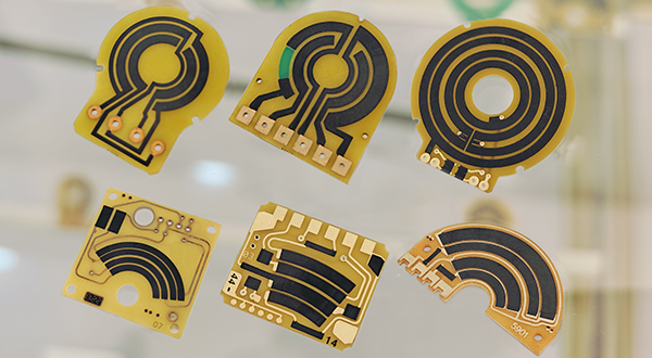
Custom Thick Film Sensors
- Custom Thick Film Sensor Elements
- Fuel Level Sensor PCB
- Fuel Level Sensor Ceramic PCB
- Oil Level Sensor Ceramic PCB
- Motorcycle Fuel Level Sensor PCB
- Throttle Position Sensor PCB
- Throttle Position Sensor FR4 PCB
- Throttle Position Sensor Ceramic PCB
- Throttle Position Sensor Flexible PCB
- Accelerator Pedal Sensor PCB
- Accelerator Pedal Position Sensor PCB
- Pedal Position Sensor Carbon PCB
- Potentiometer PCB
- Linear Potentiometer Carbon Track PCB
- Rotary Potentiometer Carbon Track PCB
- FR4 Potentiometer Carbon PCB
- Ceramic Potentiometer Carbon PCB
- Flexible Potentiometer Carbon PCB
- Logarithmic Taper Potentiometer PCB
- Position Sensor PCB
- FR4 Position Sensor Carbon PCB
- Ceramic Position Sensor Carbon PCB
- Flexible Position Sensor Carbon PCB
- Flexible Sensor PCB
- Printed Flexible Electronic PCB
- Printed Carbon PCB
- Ceramic Pressure Sensors
- Ceramic Thick Film Pressure Sensors
- Engine Oil Pressure Sensor PCB
- Gold Coated Ceramic Substrates
- Gold Coated Thick Film Substrates
- Metallized Ceramic Substrates
- Multilayer Thick Film Substrates
- Thick Film Metallization Technology
- Thin Film Metallization Technology
- Thin Film Ceramic PCB
- Variable Resistor Carbon PCB
- Remote Ready Sender Ceramic PCB
- LP Gas Tank Gauges Ceramic PCB
- Thick Film Capacitive Sensors
- Thick Film Capacitive Pressure Sensors
- Thick Film Edible Oil Quality Sensors
- Thick Film Meteorological Rainfall Sensors
- PI Interdigital Electrodes (Flexible)
- Air Door Actuator PCB
- HVAC Blend Door Actuator PCB