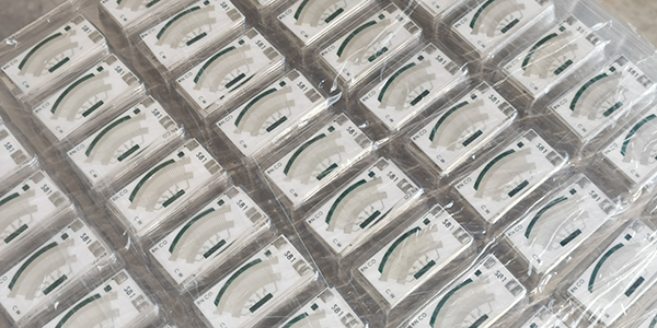
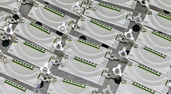
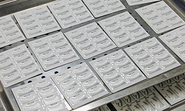
Fuel Level Sensor PCB
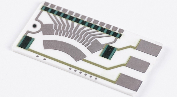
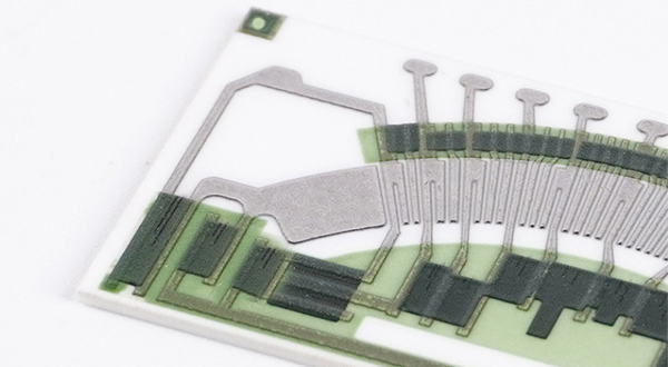
Fuel Level Sensor PCBs, also called Fuel Level Sender PCBs, are measurement components made using thick-film resistor technology with a ceramic substrate, where the sensor adjusts the resistance value based on fuel fluctuations in the tank to provide real-time data, while the ceramic substrate ensures corrosion resistance and thermal stability for long-term reliable operation in harsh environments, transmitting resistance changes to the vehicle's control system to monitor fuel consumption, remaining fuel, and optimize fuel management.
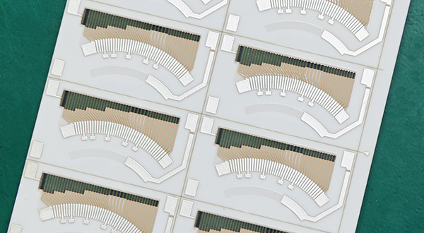
Fuel Level Sensor PCBs are primarily manufactured using thick-film technology combined with a ceramic substrate. First, conductor and resistor materials are printed onto the ceramic substrate. Then, fuel level sensor PCBs undergo a high-temperature sintering process to cure the materials, ensuring stability and reliability. Afterward, fuel level sensor PCBs are precisely adjusted through laser trimming technology to refine the resistance value and linearity, ensuring the sensor achieves the required measurement accuracy and functionality. This process guarantees that the sensor provides high-precision measurement results even under extreme operating conditions.
Fuel Level Sender PCBs offer outstanding measurement accuracy and stability. Fuel level sensor PCBs leverage thick-film resistor technology to ensure reliability under various environmental conditions, while the ceramic substrate provides excellent corrosion resistance and high-temperature stability, making it suitable for harsh working conditions. Fuel level sensor PCBs use laser trimming technology to ensure precise adjustment of the resistance value, providing superior adaptability and precision. Overall, fuel level sensor PCBs are an ideal choice for high precision, long service life, and reliability.
Fuel Level Sender PCBs are widely used in the automotive industry, integrated into vehicle fuel tanks to provide real-time fuel monitoring for drivers. Fuel level sensor PCBs are also applied to other mechanical equipment that requires fuel level monitoring, ensuring efficient and safe operation. By providing accurate fuel level and consumption data, fuel level sensor PCBs play a vital role in preventing fuel waste, optimizing performance, and improving fuel management. Fuel level sensor PCBs are an indispensable key component in modern vehicles and equipment.
Features of Fuel Level Sensor PCB :
● High Precision Measurement: Utilizing thick-film technology, the Fuel Level Sensor PCB offers high-resolution readings of fuel levels.
● Robust Construction: Engineered to withstand harsh environments, including vibrations, temperature fluctuations, and exposure to fuels.
● Compatibility: Designed to be compatible with a wide range of fuel sensors and vehicle systems.
● Reliability: Built with high-quality materials to ensure long-term operation without failure.
● Easy Integration: Fuel Level Sensor PCBs are designed for seamless integration with existing fuel monitoring systems.
Advantages of Fuel Level Sensor PCB :
Fuel Level Sensor PCBs are critical components in the operation of vehicles and other machinery that rely on fuel. Here are some advantages of using fuel level sensor PCBs:
● Improved Fuel Management: Fuel Level Sensor PCBs provide real-time data, enabling automatic alerts for fuel refills, leaks, or pilferage. They can be integrated with fleet management software to enhance operational efficiency.
● Increased Vehicle Efficiency: By offering accurate fuel level updates, fuel level sensors help in making informed decisions about fuel refilling and vehicle maintenance, potentially increasing the overall efficiency of a fleet.
● Enhanced Safety: They can detect abnormal fuel drainage, which may indicate a leak, and help prevent fuel pilferage by monitoring route deviations and fuel consumption patterns.
● Cost Savings: Detailed fuel reports from these sensors can help analyze fuel efficiency, identify areas for improvement, and make strategic decisions regarding fuel procurement and vehicle operations, leading to reduced fuel and fleet costs.
● Reduced Downtime: Live updates from fuel level sensors prevent unexpected fuel runouts, which can cause downtime and affect customer satisfaction.
● Lesser Stress on the Environment: By optimizing fuel usage and reducing wastage, fuel level sensors indirectly contribute to environmental sustainability by minimizing carbon emissions.
Applications of Fuel Level Sender PCB :
● Automotive Industry: Cars, trucks, and buses rely on Fuel Level Sender PCBs for accurate fuel gauging, ensuring drivers have real-time data for fuel management and efficiency.
● Marine Applications: Boats, ships, and other watercraft use these sensors to monitor fuel levels in their tanks, helping ensure smooth and safe navigation.
● Agricultural Machinery: Tractors, harvesters, and other heavy agricultural machinery depend on Fuel Level Sender PCBs for efficient fuel management, reducing downtime and improving operational productivity.
● Military Vehicles: Armored vehicles, tanks, and other military transport vehicles rely on Fuel Level Sender PCBs for mission-critical fuel monitoring, especially in demanding and harsh operational environments.
● Motorcycles: These sensors help monitor fuel levels in motorcycles, optimizing fuel efficiency and ensuring riders can manage fuel consumption effectively.
● Aircraft: For certain smaller aircraft, Fuel Level Sender PCBs are utilized to monitor fuel levels in their engines, ensuring optimal flight performance and safety.
● Heavy Machinery: These sensors are used in bulldozers, excavators, and other construction machinery to monitor fuel levels, ensuring smooth operation and avoiding fuel-related disruptions.
● Recreational Vehicles: Fuel Level Sender PCBs are also used in RVs and campers to manage fuel efficiency and ensure adequate fuel levels during long trips.
● Electric Generators: These sensors can be applied in generators, particularly in remote locations, to manage fuel consumption and maintain uninterrupted power supply.
Why Deed to Customize Fuel Level Sensor PCB ?
● Specific Application Requirements: Different vehicles and machinery have unique fuel tank shapes, sizes, and operating conditions. Custom Fuel Level Sensor PCBs allow for the design to be tailored to meet these specific requirements.
● Compatibility with Existing Systems: Integrating a new sensor into an existing monitoring or control system can be challenging without customization. A Custom Fuel Level Sensor PCB can ensure seamless compatibility with the existing electrical and software systems.
● Enhanced Performance: Custom Fuel Level Sensor PCBs can optimize the performance of the sensor, including its sensitivity, accuracy, and response time, to suit particular operational demands.
● Environmental Adaptability: Operating environment can vary greatly from one application to another. Customization allows for the incorporation of features that make the PCB more resilient to temperature extremes, humidity, and exposure to corrosive substances.
● Regulatory Compliance: Different regions and industries may have specific regulatory requirements for fuel monitoring systems. A customized PCB can be designed to meet these standards.
● Cost Efficiency: By customizing the PCB to include only the necessary components and features, manufacturers can reduce unnecessary costs and create a more cost-effective solution.
● Miniaturization: In some applications, space is at a premium. Customization can lead to the development of more compact and lightweight PCBs that fit within tight spaces.
● Rapid Prototyping and Iteration: Customization allows for quicker prototyping and iteration of the design, enabling faster development cycles and quicker response to changing requirements or feedback.
● Brand Differentiation: Custom Fuel Level Sensor PCBs can help differentiate a product in a competitive market by offering unique features or capabilities that competitors do not have.
● Future-Proofing: Custom designs can incorporate flexibility to accommodate future technological advancements or changes in system requirements.
Design Considerations of Fuel Level Sender PCB :
● Ceramic Substrate: Can be 96% or 98% Alumina (Al2O3), Aluminum Nitride, or Beryllium Oxide (BeO), thickness range can be 0.25, 0.38, 0.50mm, 0.635mm, 0.76mm, 1.0mm, (default thickness). Thicker thickness such as 1.2mm, 1.6mm or 2.0mm can be customized.
● Conductor Layer Materail: Silver-palladium, Gold-palladium, or Mo/Mu+Ni (for Ozone).
● Thickness of Conductor: 12um+/-5um normally, and Max can be 20um (0.02mm).
● Resistance Stability: The resistance value changes by no more than 1% in the temperature range from -40 degrees Celsius to +125 degrees Celsius.
● Solvent Resistance: After soaking in 93# gasoline for 1000 hours, there is no abnormal change in resistance value.
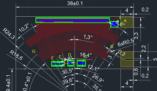
● Min Trace Width and Space: can be 0.30mm/0.30mm for volume production , and 0.20mm/0.20mm is also okay, but cost will be higher, 0.15mm/0.20mm only available for prototype.
● Tolerance for Final Trace Layout: to be +/-10% normally, Resistor value +/-1.0 ohm (or +/-1.0%) with laser trimming.
● Workable Conductors: Both gold and silver palladium is workable for gold-wire bonding, but customer need to mention that so that we will use special silver palladium which is suitable for that artwork.
● Gold Palladium: Gold palladium is much more expensive than silver palladium, about 5~10 times higher.
● Different Resistor: More different resistors designed on the same board, more expensive the board will be.
● Conductor Layer: Ceramic PCB layer can be 1-Layer and 2-Layers (with plated through hole (PTH), and plated material is the same like the one used for conductor).
● Solder Mask: Overglazes or called Glass Glaze is also available upon request, working temperature >500 C, and color can be green, blue, black, and semi-transparent.
● Abrasion Resistance (Durability): The spring wiper (contact) applies a load (loading pressure) of 0.25±0.5N on the resistance piece. Under this pressure, it undergoes one cycle of sliding back and forth in D40 test liquid.
# Dry friction Test: Frequency: 0.5 Hz to 2 Hz, Life time (cycles) >= 200,000, meets the requirements for various resistance values.
# Wet friction Test: Frequency: 0.5 Hz to 2 Hz, Life time (cycles) >= 2,000,000, meets the requirements for various resistance values.
● Adhesion: The bonding between the conductor and the ceramic plate should be firm, with a peel-off force greater than or equal to 100N.
● Unspecified linear and angular dimensional tolerances are executed according to IPC class-2.
● Unspecified dimension and position tolerances are executed according to IPC class-2.
Test Characteristics of Fuel Level Sensor PCB :
Test Item |
Standard |
Test Method |
Wear Life (Durability) |
Contact Wiper without break, Resistance within tolerances. |
Materials used for the beryllium bronze (Wipers) sliding contact area in sliding contact with the conductor layer, with the contact area pressure at 0.25 N ± 0.05 N. The test requires at least 2 million cycles in the air or 5 million cycles when immersed in gasoline or diesel. |
Resistance to Organic Solvents (Corrosion) |
(△R/R)≤ 1% |
Solvent: 85% diesel (or 92# gasoline) + 15% ethyl alcohol. Solvent temperature: (23 ± 5)°C. Soaking time: (10 ± 1) hours. |
Resistance to Soldering Heat |
(△R/R)≤ 1% |
Soldering PAD is completely immersed in a 270°C ± 5°C tin bath, maintaining (5 ± 1) seconds. Recovery time: (24 ± 4) hours. |
Temperature Coefficient (T.C.R) |
Within specified T.C.R |
As per IEC 60115-1 4.8, tested across the temperature range of +25°C/-55°C/+25°C/+125°C/+25°C. |
Rapid Temperature Changing |
(△R/R)≤ 1% |
-40°C for 30 minutes - normal temperature for 5 minutes - 85°C for 30 minutes, repeated for 5 cycles. |
Short Time Overload |
(△R/R)≤ 1% |
Apply 2.5 times rated voltage or maximum overload voltage (whichever is lower) for 5 seconds, as per IEC 60115-1 4.13. |
Endurance at 70°C |
(△R/R)≤ 1% |
70°C ± 2°C for 1000 hours with rated voltage 1.5 hours ON / 0.5 hours OFF, as per IEC 60115-1 4.25.1. |
Damp Heat Steady State |
(△R/R)≤ 1% |
As per IEC 60115-1 4.24, tested at 40°C ±2°C, 93% ±3%RH for 1000 hours. |
Low Temperature Storage |
(△R/R)≤ 1% |
Place the Fuel Level Sensor PCB in the low-temperature storage chamber at (-55 ± 1)°C, duration: 1000 hours. |
High Temperature Storage |
(△R/R)≤ 1% |
Place the Fuel Level Sensor PCB in the high-temperature storage chamber at (125 ± 1)°C, continuous for 1000 hours. |
For more information, Please refer to Thick Film Sensors.
Custom Thick Film Sensors
- Custom Thick Film Sensor Elements
- Fuel Level Sensor PCB
- Fuel Level Sensor Ceramic PCB
- Oil Level Sensor Ceramic PCB
- Motorcycle Fuel Level Sensor PCB
- Throttle Position Sensor PCB
- Throttle Position Sensor FR4 PCB
- Throttle Position Sensor Ceramic PCB
- Throttle Position Sensor Flexible PCB
- Accelerator Pedal Sensor PCB
- Accelerator Pedal Position Sensor PCB
- Pedal Position Sensor Carbon PCB
- Potentiometer PCB
- Linear Potentiometer Carbon Track PCB
- Rotary Potentiometer Carbon Track PCB
- FR4 Potentiometer Carbon PCB
- Ceramic Potentiometer Carbon PCB
- Flexible Potentiometer Carbon PCB
- Logarithmic Taper Potentiometer PCB
- Position Sensor PCB
- FR4 Position Sensor Carbon PCB
- Ceramic Position Sensor Carbon PCB
- Flexible Position Sensor Carbon PCB
- Flexible Sensor PCB
- Printed Flexible Electronic PCB
- Printed Carbon PCB
- Ceramic Pressure Sensors
- Ceramic Thick Film Pressure Sensors
- Engine Oil Pressure Sensor PCB
- Gold Coated Ceramic Substrates
- Gold Coated Thick Film Substrates
- Metallized Ceramic Substrates
- Multilayer Thick Film Substrates
- Thick Film Metallization Technology
- Thin Film Metallization Technology
- Thin Film Ceramic PCB
- Variable Resistor Carbon PCB
- Remote Ready Sender Ceramic PCB
- LP Gas Tank Gauges Ceramic PCB
- Thick Film Capacitive Sensors
- Thick Film Capacitive Pressure Sensors
- Thick Film Edible Oil Quality Sensors
- Thick Film Meteorological Rainfall Sensors
- PI Interdigital Electrodes (Flexible)
- Air Door Actuator PCB
- HVAC Blend Door Actuator PCB