Fuel Level Sensor Ceramic PCB
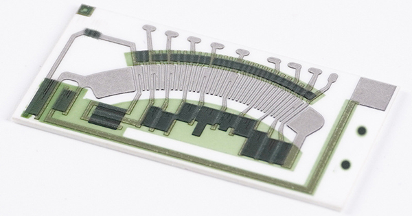
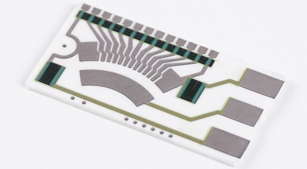
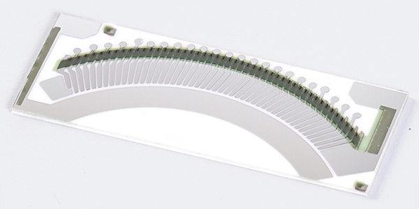
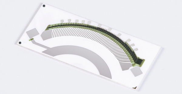
Fuel Level Sensor Ceramic PCBs, also called Ceramic Fuel Level Sensor PCBs, are critical components in modern vehicles, designed to monitor and manage fuel levels with high precision by directly integrating into the vehicle's fuel tank to measure the fuel quantity, utilizing advanced thick-film technology to ensure accurate and reliable fuel level detection while providing real-time data to the vehicle’s fuel management system, a functionality vital for maintaining optimal fuel usage, preventing overflow, and ensuring the safe operation of the vehicle.
Fuel Level Sensor Ceramic PCBs are produced using ceramic substrates and thick-film technology. Ceramic materials are chosen due to their exceptional durability, high thermal stability, and resistance to harsh chemicals, making them ideal for use in the fuel tank environment. During production, thick-film materials are applied to the ceramic substrate to create a durable sensor that can withstand extreme conditions, including exposure to fuel and fluctuating temperatures. This ensures that the sensors retain their functionality and reliability over time.
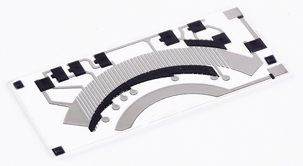
Ceramic Fuel Level Sensor PCBs combine the advantages of ceramic materials with the precision of thick-film technology. Ceramic substrates offer excellent resistance to corrosion, temperature variations, and mechanical stress, making these sensors highly durable in demanding environments. The thick-film technology allows for the precise creation of electrical components on the ceramic surface, ensuring accurate fuel level measurements. These sensors also provide long-term reliability, making them a trusted choice for automotive manufacturers focused on fuel management efficiency and safety.
Ceramic Fuel Level Sensor PCBs are widely used in the automotive industry, where they are integrated into vehicle fuel tanks for real-time fuel monitoring. These sensors are crucial for modern vehicles, ensuring efficient fuel management, preventing fuel wastage, and improving overall vehicle performance. Furthermore, their robust design makes them suitable for other applications that require precision and durability in harsh conditions, such as industrial machinery and fuel storage systems.
Advantages of Fuel Level Sensor Ceramic PCB :
● High-Temperature Resistance : Capable of withstanding the high temperatures within fuel tanks, The sensor is designed to operate within a wide temperature range, typically from -40°C to +125°C, ensuring functionality in various climates.
● Chemical Resistance : Resistant to various chemicals and fuels, ensuring long-term stability, It is resistant to common automotive fuels and their additives, as well as to oils and other chemicals that may be present in the fuel system.
● Precision Measurement : Provides accurate fuel level readings to support efficient fuel management, The sensor provides a high level of accuracy in measuring fuel levels, typically within a small percentage of the actual fuel level.
● Robust Construction : Ceramic substrate ensures the sensor's durability against physical stress and vibrations.
● Compatibility : Designed to be compatible with various fuel tank designs and vehicle models.
● Longevity : Ceramic material offers a longer lifespan compared to other materials due to its resistance to wear and corrosion.
● Reliability : Thick-film technology ensures consistent performance and high signal integrity.
● Environmental Stability : Less affected by temperature fluctuations and fuel composition changes.
● Safety : Reduces the risk of fuel leakage or overfilling by providing accurate level readings.
● Low Maintenance : Due to its robust design, the sensor requires minimal maintenance.
● Vibration Resistance : Capable of withstanding the vibrations experienced in automotive environments, ensuring long-term stability and performance.
● Mechanical Shock : Designed to endure sudden impacts without damage, maintaining sensor integrity.
● Resolution : It can detect small changes in fuel level, offering high-resolution readings for precise fuel management.
● Response Time : The sensor responds quickly to changes in fuel level, ensuring real-time monitoring.
Design Guidelines of Ceramic Fuel Level Sensor PCB :
● Ceramic Substrate: Can be 96% or 98% Alumina (Al2O3), Aluminum Nitride, or Beryllium Oxide (BeO), thickness range can be 0.25, 0.38, 0.50mm, 0.635mm, 0.76mm, 1.0mm, (default thickness). Thicker thickness such as 1.2mm, 1.6mm or 2.0mm can be customized too.
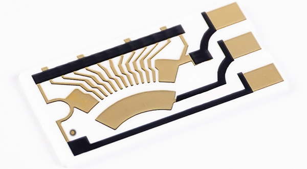
● Conductor layer materail: Silver-palladium, Gold-palladium, or Mo/Mu+Ni (for Ozone).
● Thickness of conductor: 12um+/-5um normally, and Max can be 20um (0.02mm).
● Min trace width and space: can be 0.30mm/0.30mm for volume production , and 0.20mm/0.20mm is also okay, but cost will be higher, 0.15mm/0.20mm only available for prototype.
● Tolerance for final trace layout: to be +/-10% normally, Resistor value +/-1.0 ohm (or +/-1.0%) with laser trimming.
● Both gold and silver palladium is workable for gold-wire bonding, but customer need to mention that so that we will use special silver palladium which is suitable for that artwork.
● Gold palladium is much more expensive than silver palladium, about 5~10 times higher.
● More different resistors designed on the same board, more expensive the board will be.
● Normally, ceramic PCB layer can be 1-Layer and 2-Layers (with plated through hole (PTH), and plated material is the same like the one used for conductor).
● Soldermask (overglazes or called glass glaze) is also available upon request, working temperature >500 C, and color can be green, blue, black, and semi-transparent.
Specifications of Ceramic Fuel Level Sensor PCB :
● Substrate: Ceramic plate (96% AL2O3), substrate thickness 0.64±0.1mm.
● Conductor: Silver palladium circuit is intact, without shorts or broken traces.
● Resistance stability: The resistance value changes by no more than 1% in the temperature range from -40 degrees Celsius to +125 degrees Celsius.
● Solvent resistance: After soaking in 93# gasoline for 1000 hours, there is no abnormal change in resistance value.
● Abrasion resistance (Durability): The spring wiper (contact) applies a load (loading pressure) of 0.25±0.5N on the resistance piece. Under this pressure, it undergoes one cycle of sliding back and forth in D40 test liquid.
# Dry Friction Test: Frequency: 0.5 Hz to 2 Hz, Life time (cycles) >= 200,000, meets the requirements for various resistance values.
# Wet Friction Test: Frequency: 0.5 Hz to 2 Hz, Life time (cycles) >= 2,000,000, meets the requirements for various resistance values.
● Adhesion: The bonding between the conductor and the ceramic plate should be firm, with a peel-off force greater than or equal to 100N.
● Unspecified linear and angular dimensional tolerances are executed according to IPC class-2.
● Unspecified dimension and position tolerances are executed according to IPC class-2.
Characteristics of Fuel Level Sensor Ceramic PCB :
Test Item |
Standard |
Test Method |
Wear Life (Durability) |
Contact Wiper without break, Resistance within tolerances. |
Materials used for the beryllium bronze (Wipers) sliding contact area in sliding contact with the conductor layer, with the contact area pressure at 0.25 N ± 0.05 N. The test requires at least 2 million cycles in the air or 5 million cycles when immersed in gasoline or diesel. |
Resistance to Organic Solvents (Corrosion) |
(△R/R)≤ 1% |
Solvent: 85% diesel (or 92# gasoline) + 15% ethyl alcohol. Solvent temperature: (23 ± 5)°C. Soaking time: (10 ± 1) hours. |
Resistance to Soldering Heat |
(△R/R)≤ 1% |
Soldering PAD is completely immersed in a 270°C ± 5°C tin bath, maintaining (5 ± 1) seconds. Recovery time: (24 ± 4) hours. |
Temperature Coefficient (T.C.R) |
Within specified T.C.R |
As per IEC 60115-1 4.8, tested across the temperature range of +25°C/-55°C/+25°C/+125°C/+25°C. |
Rapid Temperature Changing |
(△R/R)≤ 1% |
-40°C for 30 minutes - normal temperature for 5 minutes - 85°C for 30 minutes, repeated for 5 cycles. |
Short Time Overload |
(△R/R)≤ 1% |
Apply 2.5 times rated voltage or maximum overload voltage (whichever is lower) for 5 seconds, as per IEC 60115-1 4.13. |
Endurance at 70°C |
(△R/R)≤ 1% |
70°C ± 2°C for 1000 hours with rated voltage 1.5 hours ON / 0.5 hours OFF, as per IEC 60115-1 4.25.1. |
Damp Heat Steady State |
(△R/R)≤ 1% |
As per IEC 60115-1 4.24, tested at 40°C ±2°C, 93% ±3%RH for 1000 hours. |
Low Temperature Storage |
(△R/R)≤ 1% |
Place the Fuel Level Sensor Ceramic PCB in the low-temperature storage chamber at (-55 ± 1)°C, duration: 1000 hours. |
High Temperature Storage |
(△R/R)≤ 1% |
Place the Fuel Level Sensor Ceramic PCB in the high-temperature storage chamber at (125 ± 1)°C, continuous for 1000 hours. |
For more information, Please refer to Thick Film Ceramic PCB.
Custom Thick Film Sensors
- Custom Thick Film Sensor Elements
- Fuel Level Sensor PCB
- Fuel Level Sensor Ceramic PCB
- Oil Level Sensor Ceramic PCB
- Motorcycle Fuel Level Sensor PCB
- Throttle Position Sensor PCB
- Throttle Position Sensor FR4 PCB
- Throttle Position Sensor Ceramic PCB
- Throttle Position Sensor Flexible PCB
- Accelerator Pedal Sensor PCB
- Accelerator Pedal Position Sensor PCB
- Pedal Position Sensor Carbon PCB
- Potentiometer PCB
- Linear Potentiometer Carbon Track PCB
- Rotary Potentiometer Carbon Track PCB
- FR4 Potentiometer Carbon PCB
- Ceramic Potentiometer Carbon PCB
- Flexible Potentiometer Carbon PCB
- Logarithmic Taper Potentiometer PCB
- Position Sensor PCB
- FR4 Position Sensor Carbon PCB
- Ceramic Position Sensor Carbon PCB
- Flexible Position Sensor Carbon PCB
- Flexible Sensor PCB
- Printed Flexible Electronic PCB
- Printed Carbon PCB
- Ceramic Pressure Sensors
- Ceramic Thick Film Pressure Sensors
- Engine Oil Pressure Sensor PCB
- Gold Coated Ceramic Substrates
- Gold Coated Thick Film Substrates
- Metallized Ceramic Substrates
- Multilayer Thick Film Substrates
- Thick Film Metallization Technology
- Thin Film Metallization Technology
- Thin Film Ceramic PCB
- Variable Resistor Carbon PCB
- Remote Ready Sender Ceramic PCB
- LP Gas Tank Gauges Ceramic PCB
- Thick Film Capacitive Sensors
- Thick Film Capacitive Pressure Sensors
- Thick Film Edible Oil Quality Sensors
- Thick Film Meteorological Rainfall Sensors
- PI Interdigital Electrodes (Flexible)
- Air Door Actuator PCB
- HVAC Blend Door Actuator PCB