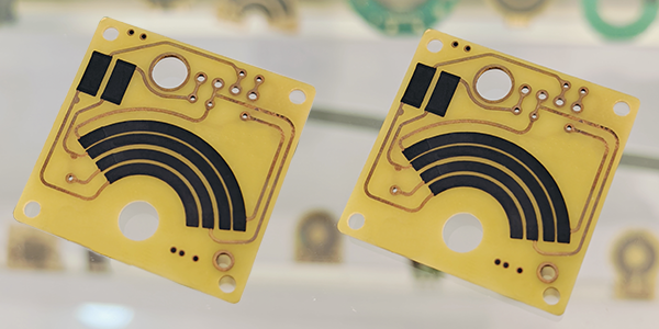
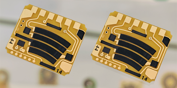
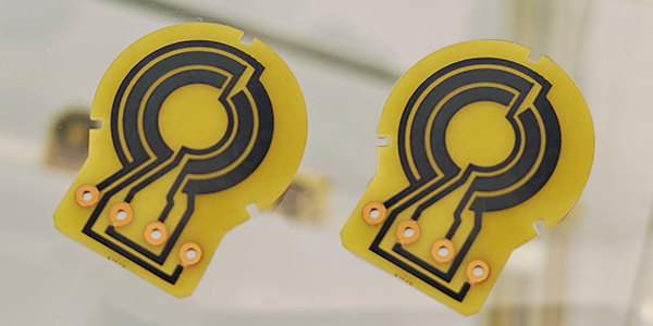
Throttle Position Sensor Carbon PCB
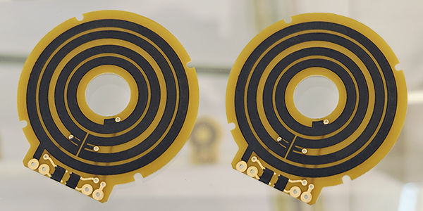
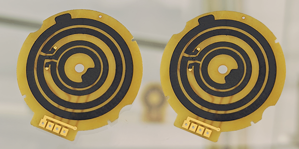
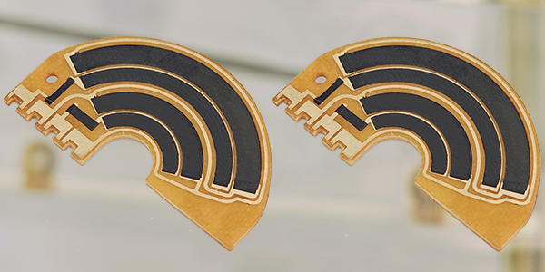
Throttle Position Sensor Carbon PCBs, also called TPS Carbon PCBs, are circuit boards designed for automotive throttle position sensors, using thick-film potentiometric technology where carbon paste is printed onto the PCBs to form carbon resistors and create potentiometric sensors, integrating variable resistors to monitor throttle positions in real-time, optimizing fuel supply and emissions control, and converting mechanical data into electrical signals to precisely adjust engine operations for optimal fuel efficiency and performance.
Throttle Position Sensor Carbon PCBs employ advanced thick-film technology, utilizing processes such as high-temperature sintering and laser repair to print carbon paste onto the PCBs, forming variable resistor potentiometric sensors. These manufacturing techniques ensure the sensors' exceptional stability and durability, allowing them to operate reliably in extreme automotive environments, particularly in high temperatures and with frequent vibrations from engines. The thick-film process not only enhances product reliability but also reduces production costs, making it a crucial technology in modern automotive sensor manufacturing.
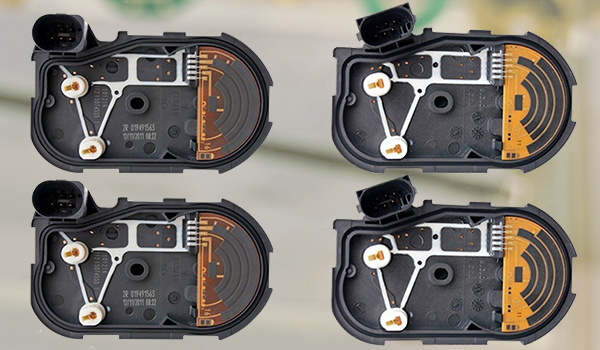
TPS Carbon PCBs are widely utilized in automotive electronic control systems, particularly in throttle position sensors. They assist the Engine Control Units in adjusting fuel injection volumes and ignition timings based on the positions of the throttles, thereby improving fuel economy and reducing emissions. Additionally, TPS Carbon PCBs play critical roles in enabling advanced features such as cruise control, traction control, and electronic stability systems. In automotive maintenance and diagnostics, failures in the throttle position sensors can result in engine starting issues, unstable idling, and poor acceleration performance. Therefore, regular inspection and maintenance of TPS Carbon PCBs are vital for proper vehicle upkeep.
Functionality of Throttle Position Sensor Carbon PCB :
● Precision Monitoring: Throttle Position Sensor Carbon PCBs can accurately monitor the degree to which the throttle is opened, that is, the extent to which the driver operates the accelerator pedal. This helps the ECU to accurately determine the operating conditions of the engine, such as idling, acceleration, or deceleration.
● Signal Conversion: The sensor converts the mechanical position of the throttle into an electrical signal, usually a voltage signal, which is proportional or inversely proportional to the throttle opening. The ECU adjusts the fuel injection quantity and ignition timing based on this signal to optimize engine performance and fuel efficiency.
● Feedback Control: The positional information provided by the throttle sensor is part of a closed-loop control system, where the ECU uses this information for real-time adjustments to ensure stable engine operation under various conditions.
● Durability: Due to the carbon film technology, these sensors typically have a long service life and good durability, capable of stable operation in the harsh environment of automotive engines.
● Fault Diagnosis: When the throttle sensor fails, such as inaccurate signals or circuit board damage, it can lead to a decline in engine performance, such as unstable idling or lack of power during acceleration. Modern vehicles are usually equipped with diagnostic systems that can identify and locate problems through fault codes.
● Wide Application: Throttle Position Sensor Carbon PCBs are not only used in automobiles but also widely applied in motorcycles, trucks, industrial machinery, and other internal combustion engine electronics.
Processes of Throttle Position Sensor Carbon PCB :
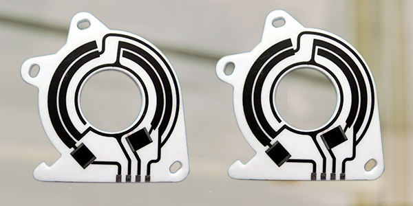
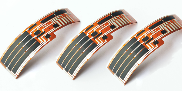
● Substrate Selection: Materials such as FR4, Ceramic, Flexible PI are commonly used as the substrate for PCBs. These materials offer good electrical insulation properties and mechanical strength, making them suitable for the usage environment of automotive electronic products.
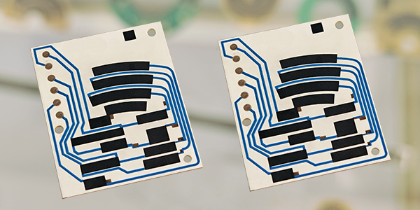
● Circuit Etching or Conductor Printing: A pattern of copper foil is etched on the substrate or conductive (Ag/Pd) paste is printed to form the required circuit pattern. This step is crucial for achieving the circuit connections on the board.
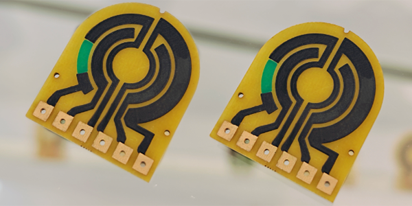
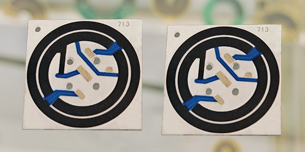
● Carbon Paste Printing: Carbon paste printing process deposits a layer of carbon-based resistor onto the PCB, creating a potentiometric sensor. This carbon layer has resistive properties and can change its resistance value as the sliding contact moves across the carbon film, thus monitoring the position of the throttle.
● High-Temperature Sintering: After the carbon paste printing, a high-temperature sintering process is required to cure the carbon paste onto the PCB, forming a stable resistive layer. This step ensures the durability and reliability of the resistive layer.
● Laser Trimming: Laser trimming technology is used to make precise adjustments to the carbon film resistance to meet specific resistance values and linearity requirements, improving the accuracy of the sensor.
● Polishing Process: Polishing process is used to improve the smoothness and durability of the carbon resistor surface, which is crucial for ensuring the stable operation and long-term reliability of the potentiometric sensor.
● Insulating Layer: Insulating material is applied over the conductor or carbon film resistance to prevent short circuits between circuits and to provide protection. The choice of material and processing of the insulating layer significantly affects the product's insulating performance and long-term stability.
Material Comparison of TPS Carbon PCB :
In the field of automotive electronics, the choice of substrate material for TPS Carbon PCBs are crucial to meet specific performance requirements. Here is a comparison of the advantages and disadvantages of using FR4, Ceramic, and Flexible Polyimide (PI) as substrate materials for TPS Carbon PCBs:
▲ Advantages:
● Cost-effectiveness: FR4 is a low-cost material suitable for mass production.
● Good electrical properties: It has a stable dielectric constant and moderate dielectric loss, making it suitable for a variety of electronic applications.
● Mechanical strength: FR4 has high mechanical strength and rigidity, making it ideal for rigid PCBs.
● Easy processing: FR4 is easy to process and laminate, fitting various PCB manufacturing processes.
▲ Disadvantages:
● Moisture absorption: FR4 is prone to absorbing moisture, which can affect the reliability of the circuit.
● Limited thermal conductivity: FR4 does not have high thermal conductivity, which may not be suitable for applications with high heat dissipation requirements.
▲ Advantages:
● High-temperature stability: Ceramic materials have a high glass transition temperature (Tg), making them suitable for high-temperature operating environments.
● Excellent thermal conductivity: Ceramic substrates like aluminum oxide have higher thermal conductivity than FR4, which aids in heat dissipation.
● Low dielectric constant: Ceramic materials typically have a lower dielectric constant, which is beneficial for high-frequency applications.
● Chemical stability: Ceramic materials are resistant to chemical corrosion and environmental changes.
▲ Disadvantages:
● High cost: Compared to FR4, ceramic materials are more expensive.
● Fragility: Ceramic materials are brittle and can break easily during processing and handling.
3, Flexible Polyimide (PI) Substrate:
▲ Advantages:
● Flexibility: PI materials offer good flexibility, making them suitable for applications that require bending or movement.
● High-temperature resistance: PI materials can maintain performance in high-temperature environments, with a Tg typically higher than FR4.
● Excellent electrical insulation: PI materials have good electrical insulation properties.
● Chemical resistance: PI materials are resistant to a variety of chemical reagents.
▲ Disadvantages:
● High cost: PI materials are usually more expensive than FR4.
● Processing difficulty: Processing PI materials can be more complex and challenging compared to FR4.
When selecting the substrate material for TPS Carbon PCBs, it is necessary to weigh the pros and cons of these materials based on the specific requirements of the application. For example, if the application requires high-temperature stability and excellent thermal conductivity, ceramic may be the better choice. If the application requires cost-effectiveness and good electrical properties, FR4 may be the more appropriate choice. And if the application requires flexibility, PI materials may be essential. Each material has its unique performance characteristics, suitable for different application scenarios.
Why Linearity Important for TPS Carbon PCBs ?
In the production of Throttle Position Sensor Carbon PCBs (TPS Carbon PCBs), the accuracy of the resistance value and the linearity of the resistance are two critical characteristics. The accuracy of the resistance value refers to how close the actual resistance value is to the nominal value, while the linearity of the resistance pertains to the consistency and predictability of the resistance value change with the throttle position.
● Accuracy of Resistance Value: Ensures the stability and reliability of the sensor output signal, which is crucial for accurate monitoring of the throttle position. Focusing solely on the accuracy of the resistance value while neglecting linearity can lead to inconsistent sensor performance across different throttle openings.
● Linearity of Resistance: Provides consistency in the resistance value change across the entire measurement range, which is essential for precisely controlling the engine's air intake and fuel injection. High linearity means that there is a good correlation between the sensor output and the throttle position throughout the entire range from fully closed to fully open, ensuring that the engine control system can accurately regulate engine performance. By the way, Achieving high linearity may require more complex production processes and stricter quality control, which could increase production costs.
Controlling linearity is often more critical in production than the accuracy of the resistance value because linearity directly affects how the Engine Control Unit interprets the throttle position and makes subsequent control decisions. If linearity is insufficient, even high resistance value accuracy can lead to unstable engine performance, such as unstable idling and inaccurate acceleration response. Moreover, since the throttle position sensor is frequently used under partial loads, nonlinear behavior is amplified in this critical area, affecting overall performance. Therefore, improving linearity of TPS Carbon PCBs through techniques such as laser trimming can significantly enhance the sensor's long-term stability and reliability.
Characteristics of TPS Carbon PCB :
Test Item |
Standard |
Test Method |
Linearity of Output Voltage |
Should be ≤ 1% |
Throttle Position Sensor PCB must maintain a linearity of output voltage that should not exceed ±1% to ensure precise throttle angle measurements. This linearity is tested by recording the sensor's output voltage in relation to the throttle's angular position over multiple full-range cycles. |
Wear Life (Durability) |
Over 5 million cycles |
Throttle Position Sensor PCB utilizes a platinum-palladium alloy wire sliding contact wiper, which ensures durability and reliability. The contact pressure with the resistive body is maintained at 0.15 N ± 0.05 N, and the sensor is designed to endure at least 5 million cycles of operation. |
Temperature Coefficient |
Within specified T.C.R |
Throttle Position Sensor PCB's resistive temperature coefficient is kept within specified limits as per IEC 60115-1 4.8, ensuring stable performance across a range of temperatures from +25°C to -40°C, and up to +125°C. |
Short Time Overload |
(△R/R)≤ 5% |
Throttle Position Sensor PCB is tested for short time overload conditions by applying a voltage of 16V for a period of 60 minutes, ensuring it can handle temporary voltage spikes. |
Rapid Temperature Changing |
(△R/R)≤ 5% |
Throttle Position Sensor PCB is subjected to rapid temperature changes, with cycles of -40°C for 30 minutes, a transition to normal temperature for 5 minutes, and then 125°C for 30 minutes, repeated for 5 cycles. |
Low Temperature Operation |
(△R/R)≤ 5% |
Throttle Position Sensor PCB's low-temperature operation is tested by placing it in a low-temperature chamber at -40°C, maintaining the temperature for 1 hour, and then applying a nominal voltage of (5 ± 0.1) V for 48 hours. |
Endurance at 70°C |
(△R/R)≤ 5% |
Throttle Position Sensor PCB's endurance is evaluated at a constant temperature of 70°C ± 2°C for 1000 hours, with a cycle of 1.5 hours ON and 0.5 hours OFF, using the rated voltage or the limiting element voltage, whichever is lower. |
Damp Heat Steady State |
(△R/R)≤ 5% |
Throttle Position Sensor PCB's performance in damp heat conditions is assessed at 40°C ±2°C and 93% ±3%RH for 1000 hours. |
Low Temperature Storage |
(△R/R)≤ 5% |
Thick Film Resistor is tested for storage at low temperatures of -40°C ±1°C for 1000 hours to ensure long-term stability. |
High Temperature Storage |
(△R/R)≤ 5% |
Thick Film Resistor is also tested for storage at high temperatures of 150°C ±1°C for 1000 hours to evaluate its resistance to prolonged exposure to heat. |
For more information, Please refer to Thick Film Sensors.
Custom Thick Film Sensors
- Custom Thick Film Sensor Elements
- Fuel Level Sensor PCB
- Fuel Level Sensor Ceramic PCB
- Oil Level Sensor Ceramic PCB
- Motorcycle Fuel Level Sensor PCB
- Throttle Position Sensor PCB
- Throttle Position Sensor FR4 PCB
- Throttle Position Sensor Ceramic PCB
- Throttle Position Sensor Flexible PCB
- Accelerator Pedal Sensor PCB
- Accelerator Pedal Position Sensor PCB
- Pedal Position Sensor Carbon PCB
- Potentiometer PCB
- Linear Potentiometer Carbon Track PCB
- Rotary Potentiometer Carbon Track PCB
- FR4 Potentiometer Carbon PCB
- Ceramic Potentiometer Carbon PCB
- Flexible Potentiometer Carbon PCB
- Logarithmic Taper Potentiometer PCB
- Position Sensor PCB
- FR4 Position Sensor Carbon PCB
- Ceramic Position Sensor Carbon PCB
- Flexible Position Sensor Carbon PCB
- Flexible Sensor PCB
- Printed Flexible Electronic PCB
- Printed Carbon PCB
- Ceramic Pressure Sensors
- Ceramic Thick Film Pressure Sensors
- Engine Oil Pressure Sensor PCB
- Gold Coated Ceramic Substrates
- Gold Coated Thick Film Substrates
- Metallized Ceramic Substrates
- Multilayer Thick Film Substrates
- Thick Film Metallization Technology
- Thin Film Metallization Technology
- Thin Film Ceramic PCB
- Variable Resistor Carbon PCB
- Remote Ready Sender Ceramic PCB
- LP Gas Tank Gauges Ceramic PCB
- Thick Film Capacitive Sensors
- Thick Film Capacitive Pressure Sensors
- Thick Film Edible Oil Quality Sensors
- Thick Film Meteorological Rainfall Sensors
- PI Interdigital Electrodes (Flexible)
- Air Door Actuator PCB
- HVAC Blend Door Actuator PCB